We have more or less completed our Benchmill CNC upgrade project, installing Sieg 2.7 castings in place of the original mill, reinforcing the head, upgrading the power distribution, and installing a 2 HP spindle motor. We have the auto-oiling and pneumatic power drawbar installed, and everything is up and running. As icing on the cake, we are going to take advantage of the Intelitek automatic tool changer functionality built into its CNC software to support a scratch-built sled-style automatic tool changer system.
In designing an ATC system, there are a few options to consider when getting the tool to the spindle nose. The most common approach is to use a rotary carousel where an indexed platter holds the tools. This platter rotates to predefined positions to call up the requested tool, which is then clamped into the spindle using various design-dependent mechanisms. Digging through the config files for the Intelitek software, I saw that it does in fact include settings for a rotary tool changer, but that functionality is associated with a different model (Promill 8000). Rather than run the risk of building something only to find missing wiring connections into the controller that the software assumes are present, I elected to go with a more simple sled-style design.
Designing the Sled System
The Benchmill 6000 platform was originally offered with an optional tool stand for ATC functionality. The manufacturer’s stand makes use of spring-loaded standoffs to hold the tools steady while allowing a bit of play when clamping. The Intelitek software employs a fixed reference system for tool changes, allowing you to train the mill by defining the table and head position at the point where the tool is fully inserted into the spindle nose. The software recalls this position and moves the spindle to it when the tool is called for.
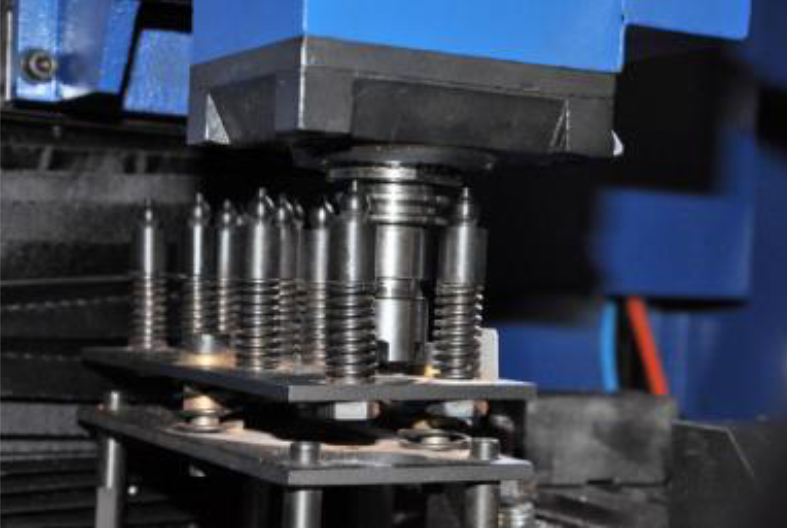
This is an exceedingly simple system, but its primary drawback is that it eats up valuable table travel with the tools and limits the number of tools that can be called up compared to the rotary platter style.
We’ll see if we can do better.
To (partially) overcome the space/capacity limitation, we’ll take advantage of the fact that the Intelitek software always raises the head to the Z-axis home position before initiating a tool change. We’ll monitor for that condition and use an air-driven cylinder that extends a shelf holding the tools into position when the machine then moves the table over to where it thinks the tool ought to be. Importantly, when the head is closer to the work, the sled will be safely retracted, maximizing the available work envelope.
To achieve this, the air cylinder will be pressurized by a solenoid that is energized once a micro-controller (we’ll be using an Arduino) detects the table and head moving to the tool change position (defined as: Z-axis at home position and the table at the far left of travel). In theory, this strategy only sacrifices the upper left quadrant of travel and allows machining along most of the table as long as the head is in the lower 80% of its Z-axis travel.
Designing the Control Logic
Before fabricating anything, we have to first make sure that we can get the Arduino reading signals from two inductive proximity sensors. One sensor will be attached to the column and will detect when the head is retracted to its home position. The other will be bolted to the front of the saddle and will detect when the table has traveled to its extreme right position (bringing the head over the extreme left side of the table).
The inductive proximity sensors I purchased (Amazon link) use 3 wires: a brown wire expecting between 3-36 volts, a blue wire that is wired to ground, and a black signal wire. As a NPN sinking sensor, when ferrous metal is in proximity to the sensor (usually within 3mm or so), the signal wire is switched to ground. This “sinking” behavior is very important, in that the sensor requires over 6 volts to operate, but the Arduino’s inputs can only take 5.5v before they fry. Were the sensor to switch the signal wire to a positive voltage, it would be disastrous for the Arduino.
In my Arduino Sketch (program), I enabled the pull-up resistor for the two assigned input ports (#2 and #4). I also hard wired a diode to the two inputs to make doubly sure that no current ever flows to the inputs. In use, the pullup resistor and the NPN sensor behavior means that the Arduino input will read “high” when the sensor is not triggered and “low” when it is in proximity to ferrous metal and switches the signal wire to ground.
With this set up, it is simple to program one of the Arduino 5V outputs to trigger once the Z-axis sensor detects the head in the home position and the X-axis sensor detects the head over the far left of the table. Once triggered, the output will remain active until the X-axis position moves away, regardless of what the Z-axis sensor reads (allowing the head to descend to pick up the tool without the sled retracting).
Here is the code:
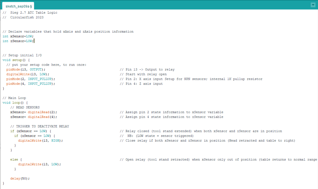
We’ll connect the output from the Arduino to a simple relay capable of switching 24V DC to drive the air solenoid that will provide pressure to a dual action air cylinder. We’ll also use a simple buck converter (Amazon link) to step down the 24 volts coming from the Benchmill power supply to 7.5V for both the Arduino and the inductive proximity sensors.
Tool Changer Construction
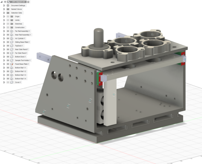
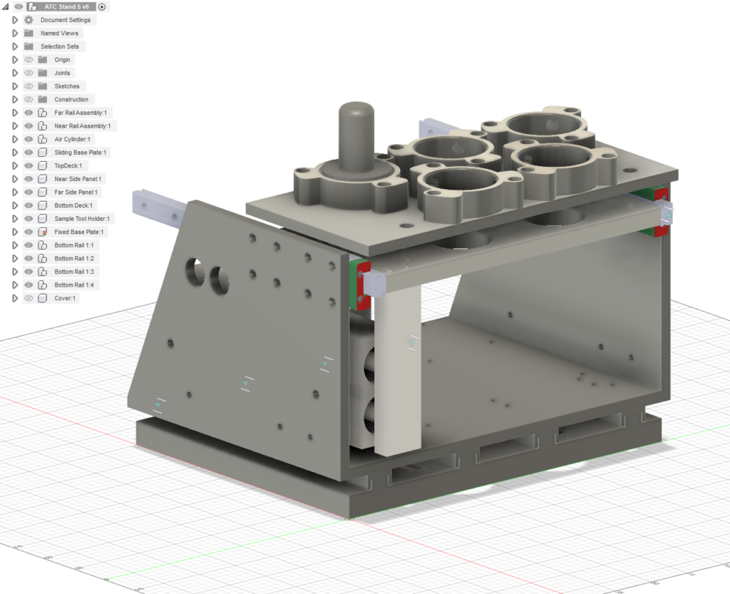
To keep weight and cost down, we’ll build the tool changer out of 1/4″ aluminum, all except a 1/2″ base plate. Between the base plate and the bottom of the changer body, we’ll install four low profile drawer slides and a spring system to keep the changer body in place but to allow the whole thing to slide backward as a safety measure in case of a collision with the head.
If you can picture this in operation, should the ATC open up into something on the table, it will just push the whole assembly backwards instead of breaking itself or what it collides with. If, conversely, the head needs to reach the extreme left side of the table when milling, it will just push the ATC out of the way. Full X-axis travel achieved.

Along the same lines, we’ll situate the top shelf of the sled into which the tools are inserted on four springs connected to a bottom deck bolted to the linear rails. This will allow the top plate to compress slightly when the spindle nose is lowered to accept the tool and give us a further margin of error to avert crashes.
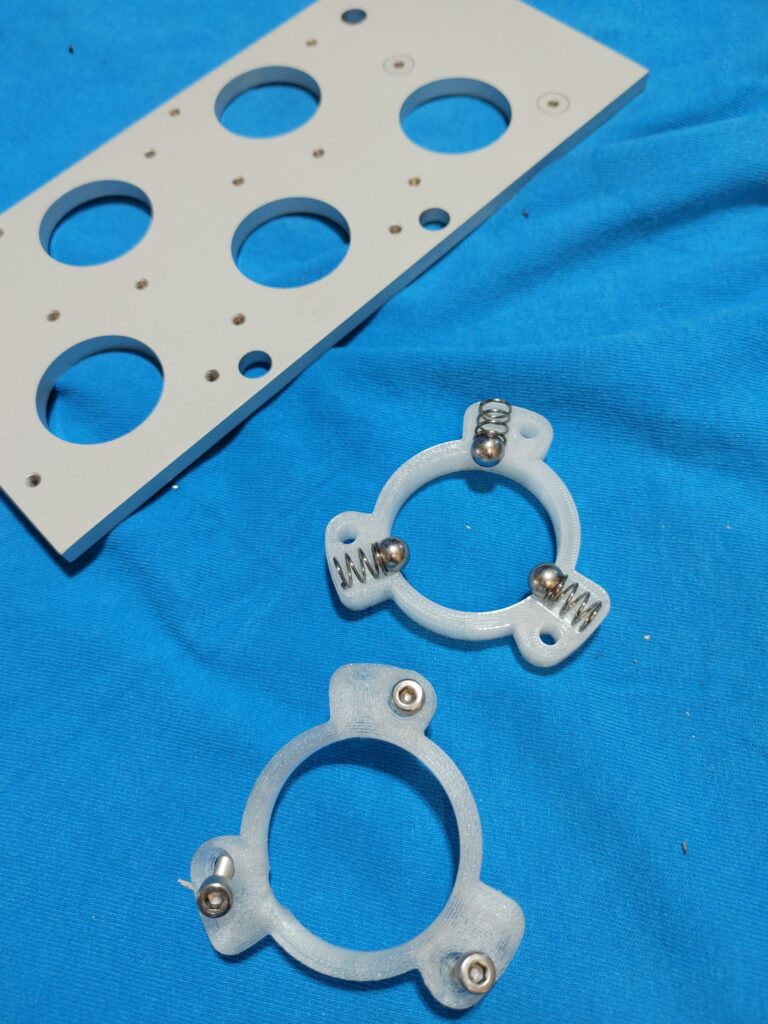
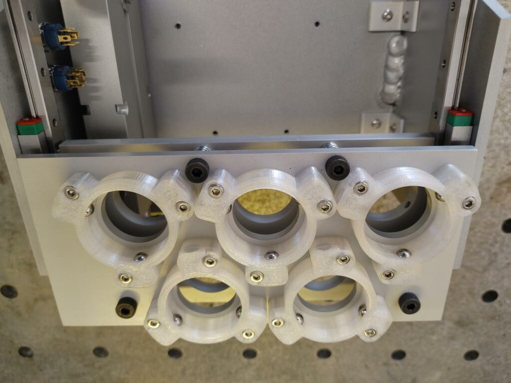
To hold the tools in the top shelf, we’ll 3D print PETG tool cradles each with three ball and spring detents. These grip the TTS tool holders along the groove cut into the skirt of each holder. This engagement will allow just enough grip to hold the tool in place when it is returned to the cradle and released by the spindle, but will remain loose enough for the tool to easily pop free when the spindle nose closes on it.
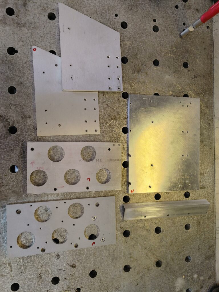
Fabricating Sliding Plates and ATC Body
Fabrication from the Fusion 360 drawings was done on the CNC machine itself. These were technically its first chips, which I dutifully recorded like a proud parent. Unfortunately, I had to reset my cell phone for unrelated reasons and lost the video, so you’ll have to take my word for it that everything worked splendidly – the design utilizes simple shapes with only circular pockets, drilled holes, and 2D outer profiles – nothing fancy.
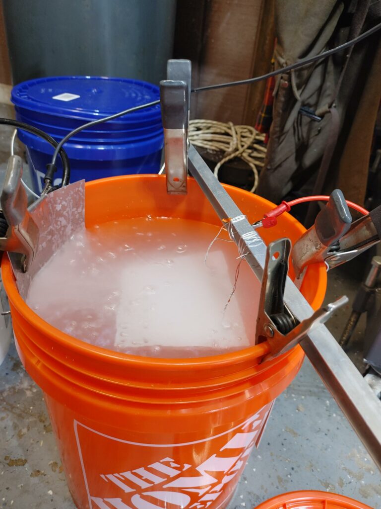
I’ve always been fascinated with anodizing, and decided that this was as good a time as any to give that process a shot. As a small detour, I built a constant current power supply capable of 24V using an ebay “silver box” power supply and a voltage/current regulator with constant current capability. The latter is important, as it allows the voltage to vary up to a set maximum as the anodized layer builds up resistance on the pieces being anodized. I used 5 gallon pails for the sulfuric acid electrolyte and the sodium hydroxide initial treatment. Worked great.
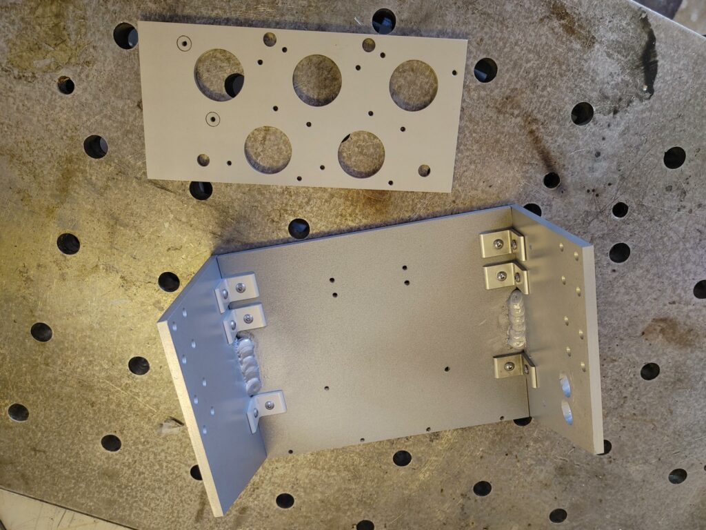
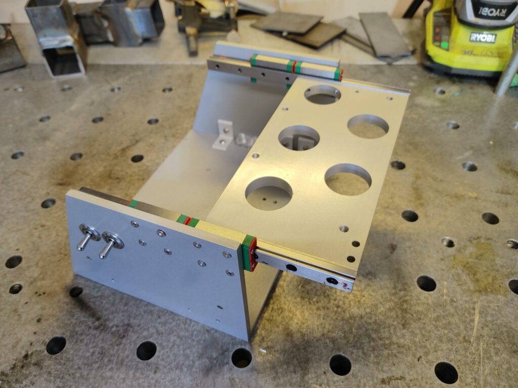
Instead of sealing the anodized parts, I clear coated them with polyurethane wheel paint, which left a nice “MacBook” like finish that became hard as a rock after curing. Here are the parts partially assembled after anodizing. (After bolting together with brackets, I added two 1-2″ inside fillet welds to hold things together).
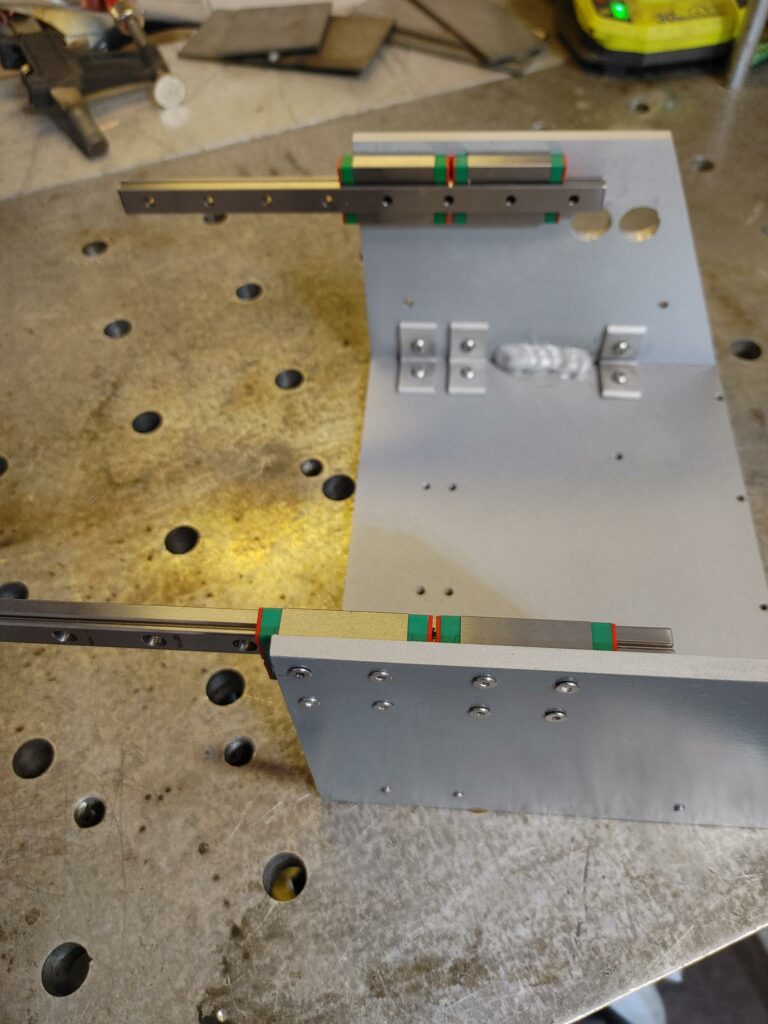
The linear rails I selected were 200mm long, 12mm wide MGN12H models (Amazon link). I used two trucks per side for added stability. These were fixed to the sides of the ATC body, allowing the rail to move and providing 8 fixing points per side.
The sliding deck and top shelf that make up the sled were just bolted on, along with the air cylinder. The cylinder I used was a dual rod, 20mm bore, 100mm stroke model (Amazon link). I added holes for two toggle switches – one to disable the unit and the other to force it to deploy for loading tools.
Here is the top assembly with the 3D printed tool holders and suspension springs installed (you can just barely see the springs between the upper and lower decks).
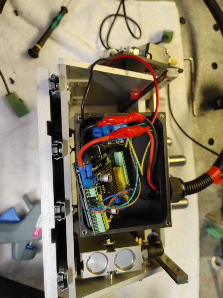
Next I installed the sliding base plate and 3D printed box holding the Arduino and relay. The air solenoid was bolted to the back of the box. I also had to fabricate a small bracket (see pic below) to tie the air cylinder to the bottom deck plate of the sled.
I installed everything in the Benchmill enclosure and rapidly saw that I could get even more travel by creating a sheet metal “pocket” into which the unit can be recessed (unpainted sheet metal to the left of the picture below).
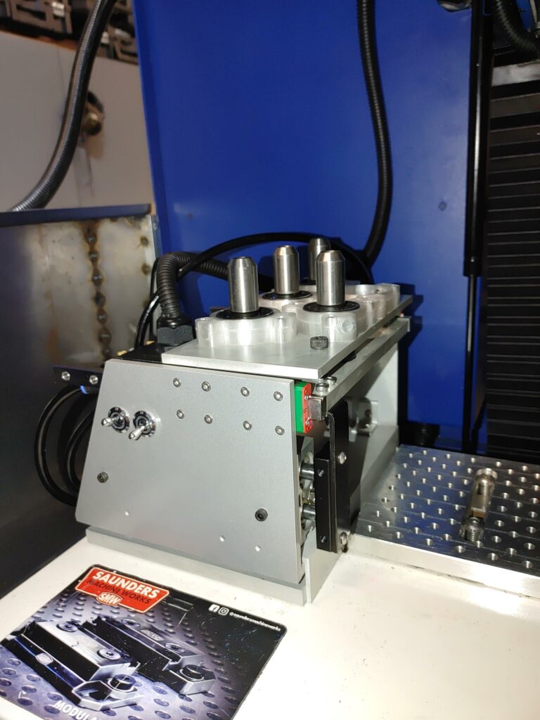
After testing to make sure that everything works, I designed a 3D printed enclosure that sits atop the ATC body and added a fold out door to keep chips out of the assembly.
Here is the completed ATC in action. As the Intelitek software calls for a tool change, you can see the desired behavior where the sled deploys only when the head is fully retracted and moved over the extreme left of the table. It remains extended, regardless of Z-axis position, until the head moves back to the right.
This works great, but I’m not totally happy yet with the door system, as the top can sometimes catch on my longer spot drill. I’ll be redesigning it slightly to reduce the profile, but for now the setup works just fine with my shorter endmills.
So as they say, that’s all folks! All in all, I’m very happy with the way the CNC project turned out. I hope keeping a good record of it has been useful to someone out here.