With the new Sieg 2.7 parts for our Benchmill 6000 CNC upgrade assembled, it is time to build something for the assembly to sit on. We could, well, just put the Benchmill enclosure on a bench, but we’ve increased the weight of the machine to the point that may become problematic. We’ve also increased the Sieg’s power over stock, and it makes sense to match that power with something a bit more rigid than a bench top. Besides, I want something that I can roll around the shop.
That said, I don’t want to spend an arm and a leg on what is essentially a fancy stand. To keep cost down, we’ll use scrap already laying around to build a 2″ square tube box with melamine panels for the walls and cabinet doors. The bottom half of the stand will be a basic cabinet, with one side dedicated to a coolant tank and the other to store a future 4th axis. Up top, we’ll have a slide out tray for the keyboard and two drawers for tooling. The whole thing will sit on adjustable, heavy duty (500lb each) casters.
None of this is particularly rocket science, so feel free to give this a skip if you’ve got cabinet making covered. That said, I have a few of these under my belt and feel that I have the process down to the point that I can construct something relatively sturdy, professional looking, fast, and cheap. If you are looking for design inspiration, read on.
In terms of that design, the Benchmill enclosure consists of two parts. The bottom is a reinforced tray, with 1″ square tube providing rigidity to the bottom. Our stand will allow this bottom tray to drop down and fit inside the top perimeter of the cabinet. It will be pinned by bolts, which, in theory, will add two layers of rigidity since the tray bottom will also rest on the top of the frame, insulated by felt pads.
Construction is relatively simple and should be straightforward for anybody with a band saw and a welder. I won’t go into too much detail since this stuff is covered in a million places elsewhere, but in a nutshell I framed the two short ends first, and tied them together with the four long cross pieces. I used a shop-built welding table to keep everything square and flat.
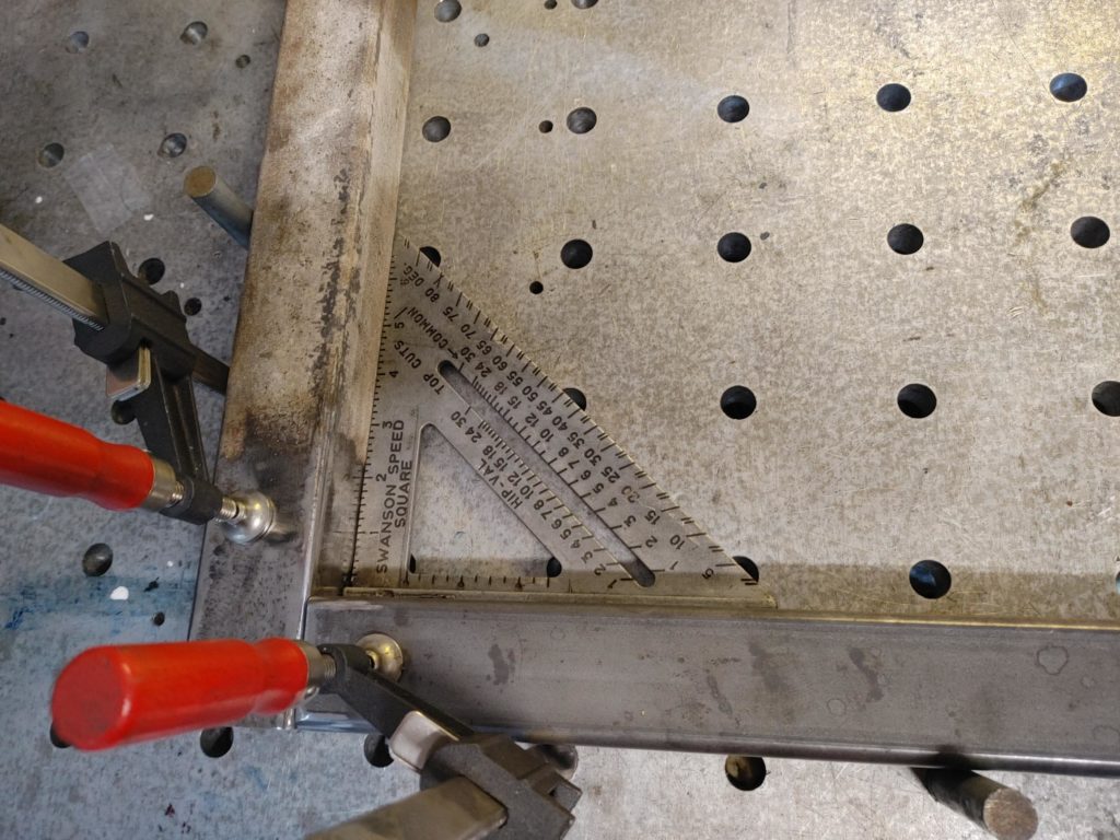
Here we are tying the two short ends together. Again, the dimensions are calculated so that the 1″ square tube welded to the bottom of the Benchmill bottom tray can drop down inside the inner perimeter of the frame.
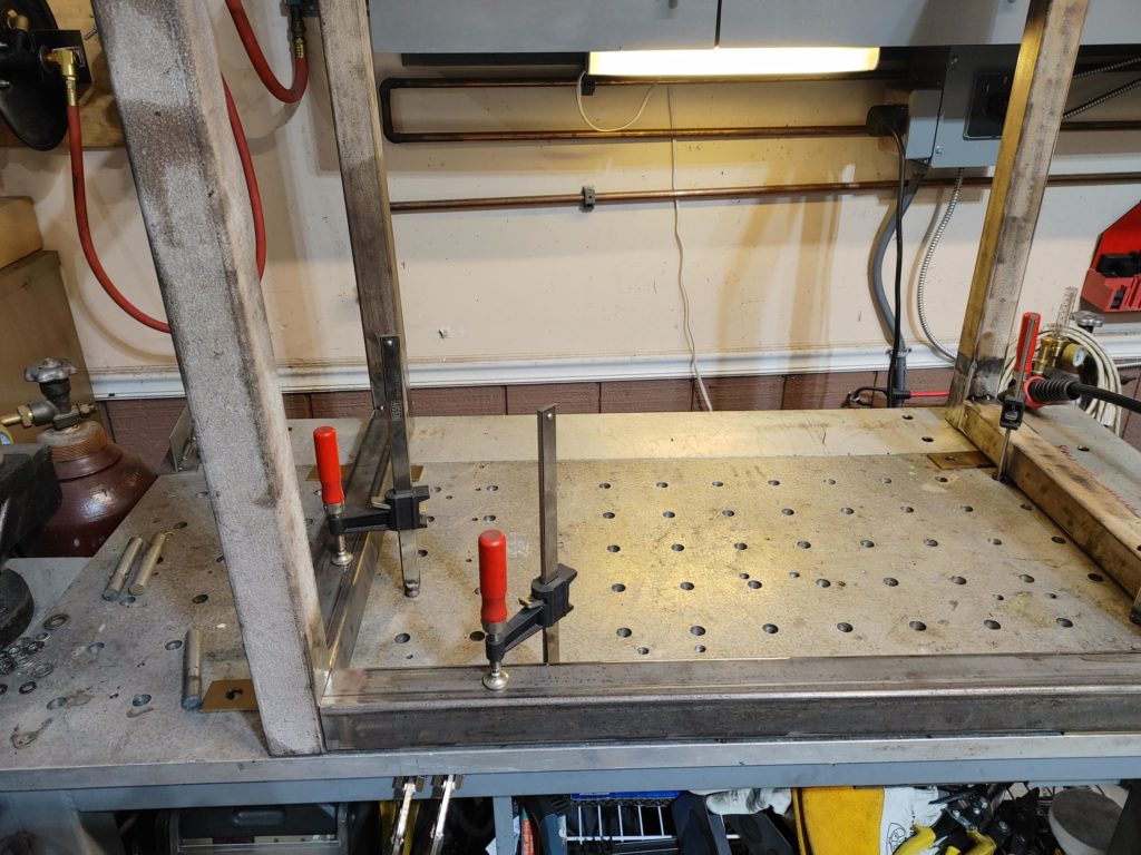
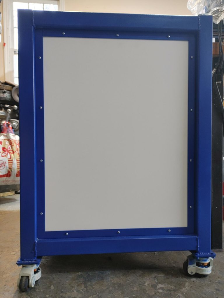
And here is the completed frame. I am no welder/fabricator, but it it ended up reasonably square. You’ll note the 1″ angle welded to the inside perimeter of the two short sides. This will allow us to mount the melamine side panels and keep everything looking nice and tidy.
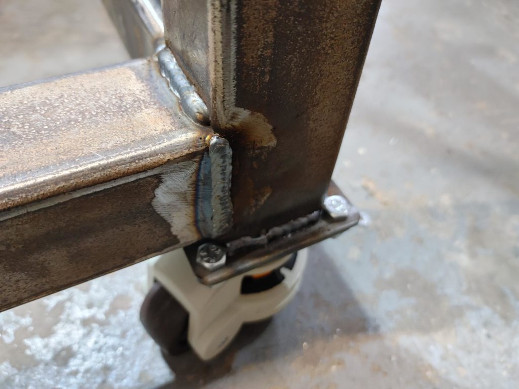
The casters are bolted to plates welded to the bottom of the square tube. These have a leveling adjustment, so that once I park the mill where I want it, I can level it and it should stay relatively steady.
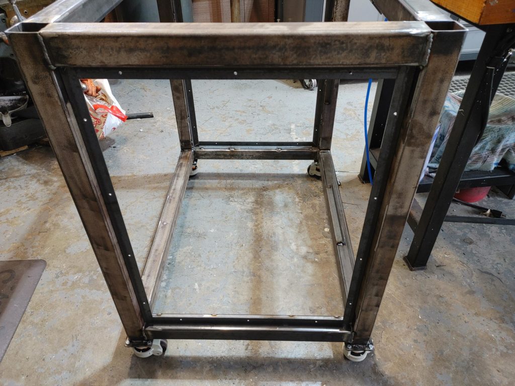
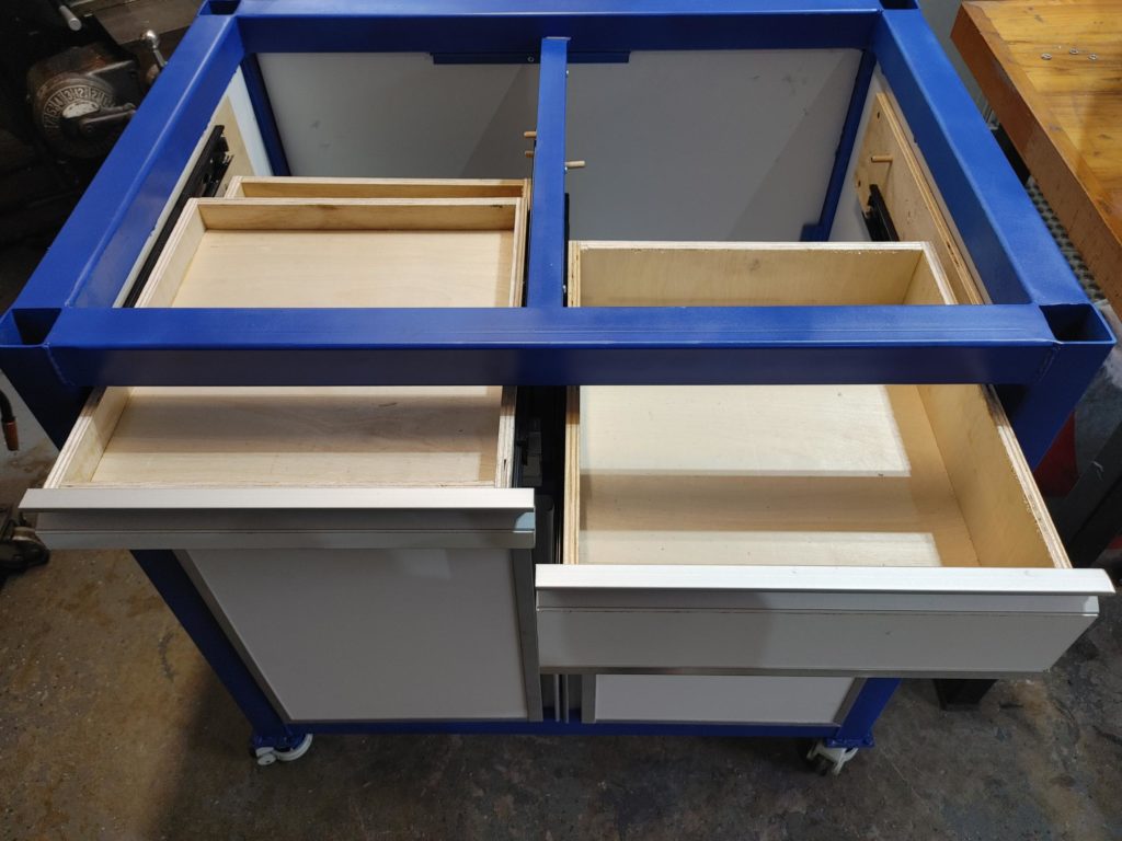
Here is the frame after some grinding, sanding and paint. You’ll note cross pieces at the top and bottom, and along the front. The bottom will support a 3/4″ plywood panel (you can see it in the background) on which the inner drawer sliders will be mounted. The top is positioned to support the underside of the tray. The piece along the front will separate the top drawers from the bottom cabinet.
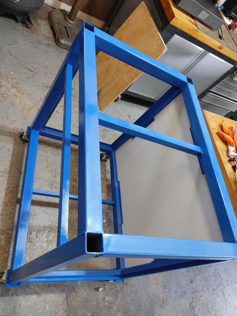
With the 1″ angle inserts welded to the short sides (and a couple along the back) it is easy to cut and mount the side panels. I’m using bog standard white melamine here, which was cheaper than plywood, fits the color scheme of the machine, and should be resistant to coolant spills.
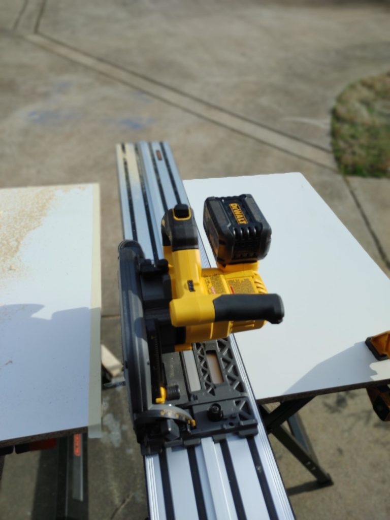
Next up, I cut the cabinet doors using a track saw.
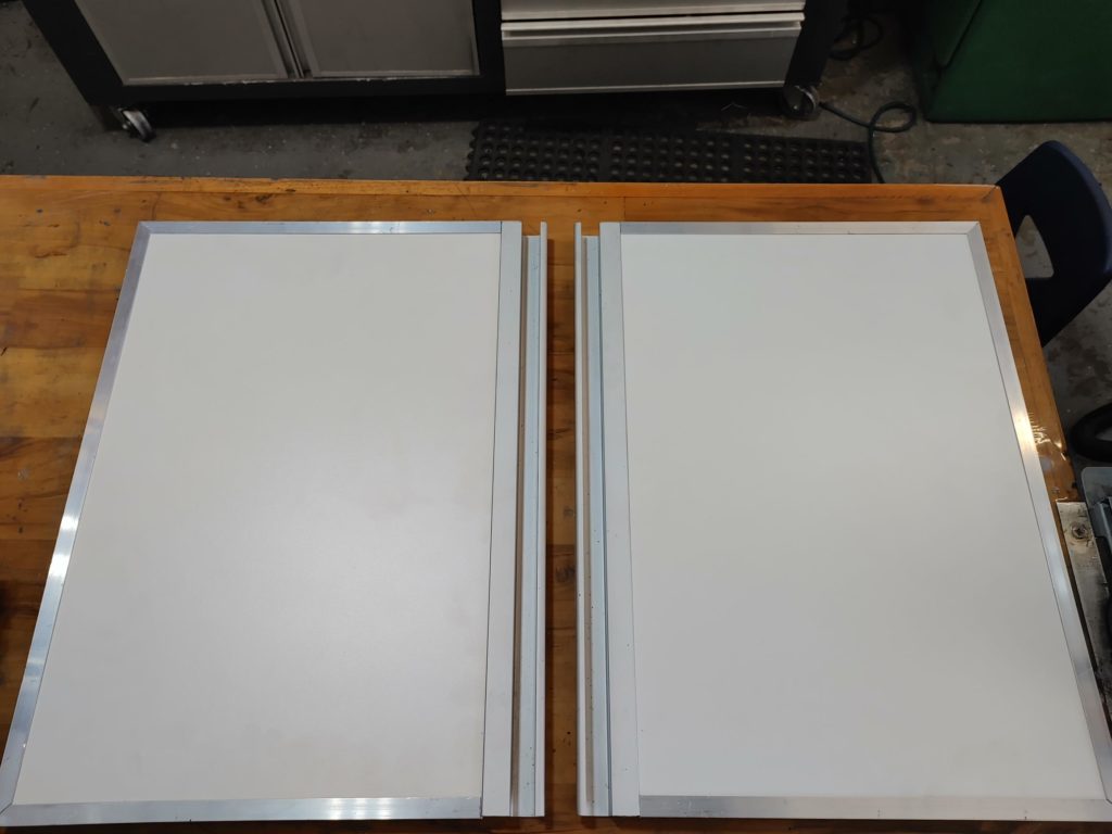
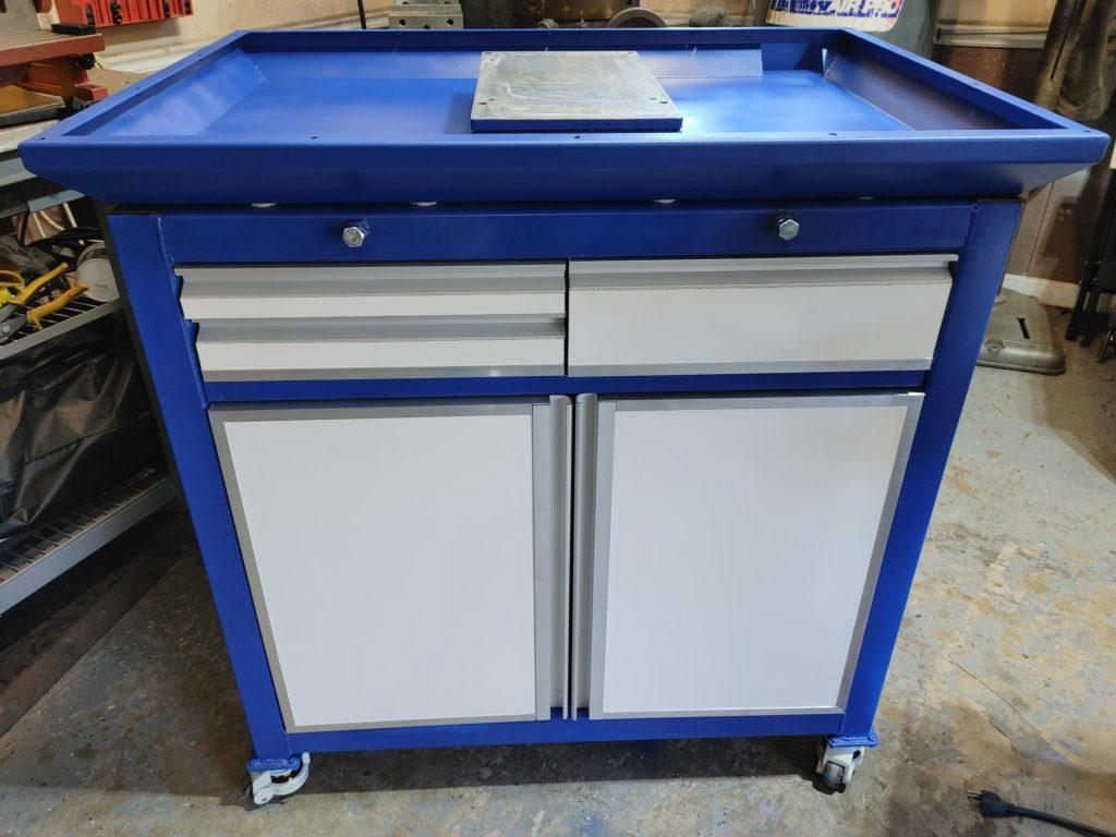
I covered the melamine cut edges with 3/4″ aluminum channel on three sides, and some leftover continuous drawer pull on the inside edge. The result looks clean and relatively professional.
I then repeated this process with the drawers. I began with1/2″ plywood drawer boxes held together with glue, brads, and in the case of the drawer which will hold tooling, 1-1/4″ wood screws. I’m not a woodworker so I didn’t mess around with fancy joinery. With the wood screw reinforcement, the result will be plenty sturdy and took less than an hour to make.
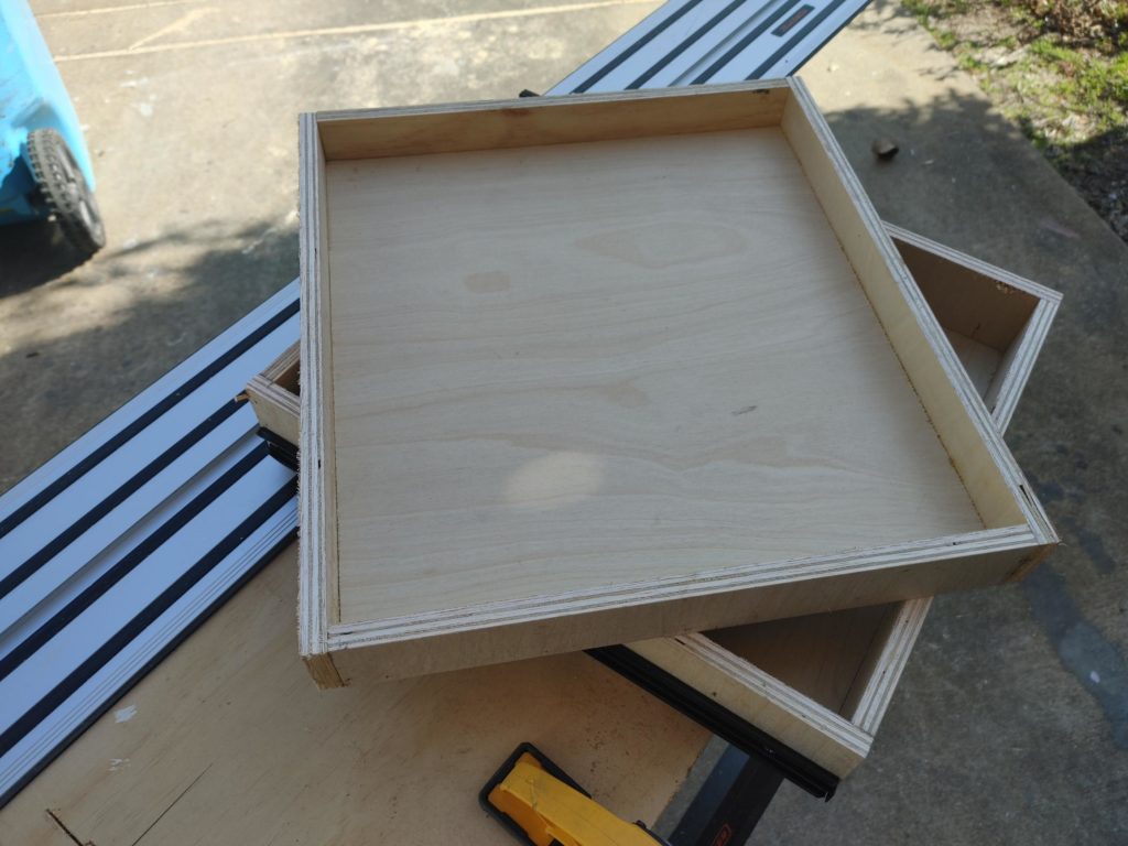
Next, I made the drawer fronts from leftover melamine. I had to use a different continuous pull and did not band the drawer bottoms. For those, I used iron-on melamine edge tape (on sale at Home Depot for $.01 – I kid you not).
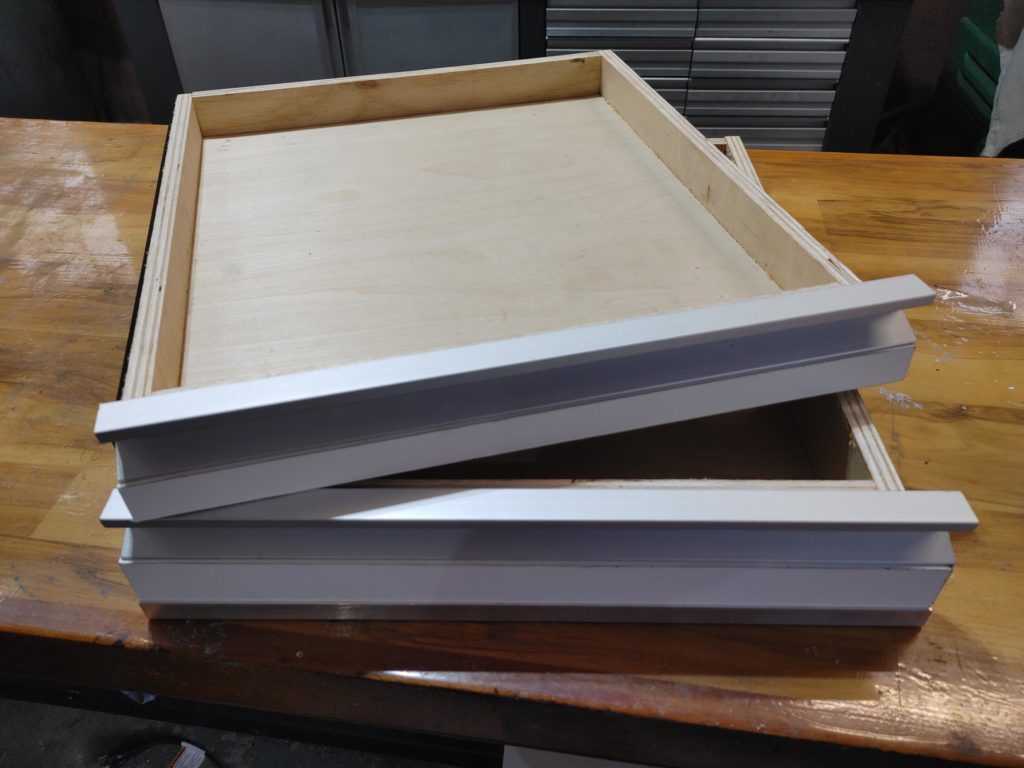
I then installed the cabinet doors with soft-close hinges. The drawer slides were attached to the melamine sides using cleats, and to the 3/4″ plywood center piece. I used dowel pins as stops to make sure the various drawers closed to the same points.
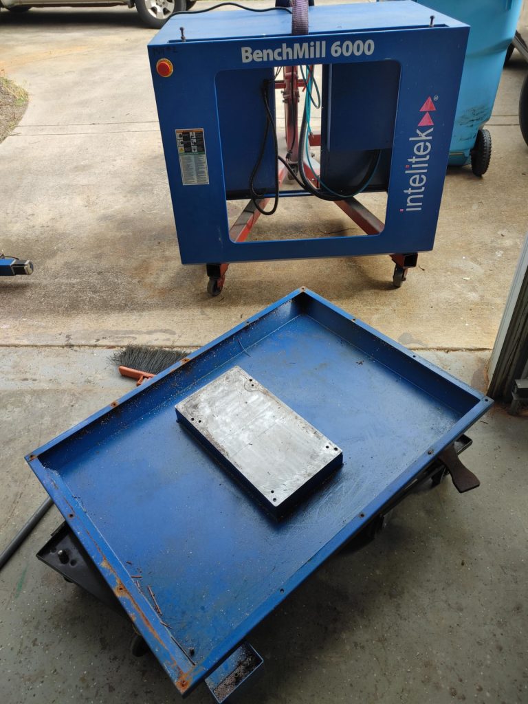
Separating the top and bottom Benchmill parts required an engine hoist. The parts are not too heavy themselves, but are exceedingly bulky.
You can see the mounting plate in the bottom tray. It almost fits the Sieg 2.7 base exactly. Some mods will be necessary to offset the mill toward the rear to clear a way cover addition (more on that later), but it is a good start. I ended up treating the rusty parts with acid, sanding and painting the tray in the same color as the cabinet frame.
And voila. You can see two bolts at the front used to pin the tray to the interior of the frame.
I estimate I have a bit less than $150 in the cabinet, including the heavy duty leveling casters which were the single most expensive component. If I’d not used shop scrap, I’d peg the total cost at around $250.
Cost aside, we now have an extremely sturdy base which can be easily leveled and rolled out of the way if needed. We’ve added storage space, including a place for tooling, a keyboard, a coolant tank, and somewhere to store the 4th axis we’ll be adding. Everything is laid out logically for the project and the effort in building a custom cabinet should pay dividends in terms of ease of use.
Next up: we’ll be 3d printing way wipers and developing a way cover system to keep that coolant and the inevitable chips out of the clockwork.
