
We’ve identified a lack of rigidity in the head and column of our import Sieg mill castings as the primary areas of concern for our CNC mill project. In a previous post we added a half-inch plate along the back of the column and made sure it was flat and parallel to the front ways. Now we’ll return and add a mechanism to stiffen the head along the column and increase overall rigidity.
The design is simple: we’ll install a pair of linear rails on the new half-inch steel column back plate. To that we’ll attach a mounting plate that rides on the rail trucks and to that, in turn, we’ll mount the ball nut holder for the eventual rear ball screw. To the sides of the mounting plate, we’ll attach two thinner (3/8″) plates that pass along the sides of the column and tie the assembly to the head casting. This will allow the ball screw to elevate the head, while adding to the overall rigidity of the setup.
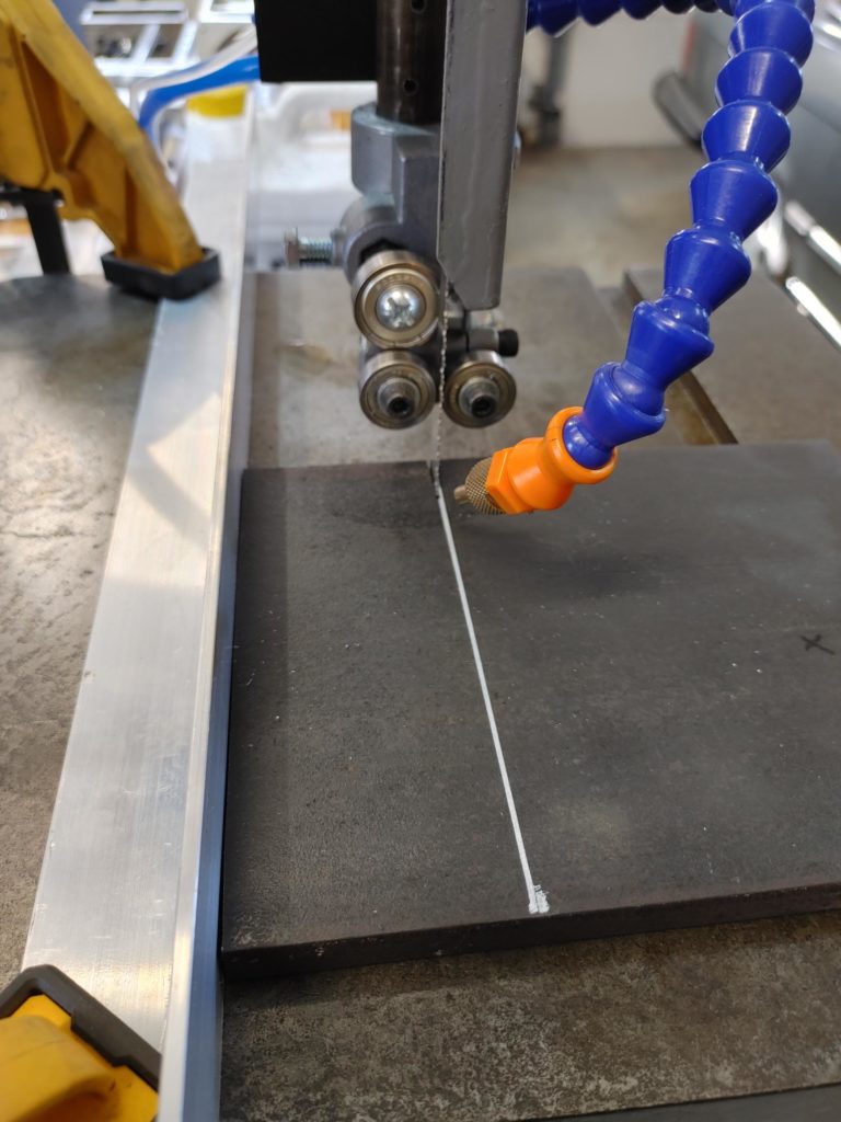
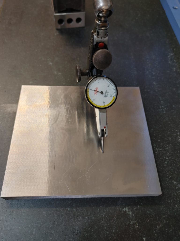
To get there, we start with a leftover piece of 1/2″ cold-rolled. I cut it on the bandsaw and finished on the mill (not pictured) to be roughly 130.5mm in width, giving a half-millimeter for side clearance. Because it is important that the assembly be flat, I threw the plate on the surface grinder.
After grinding …
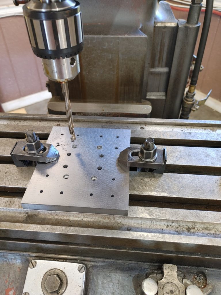
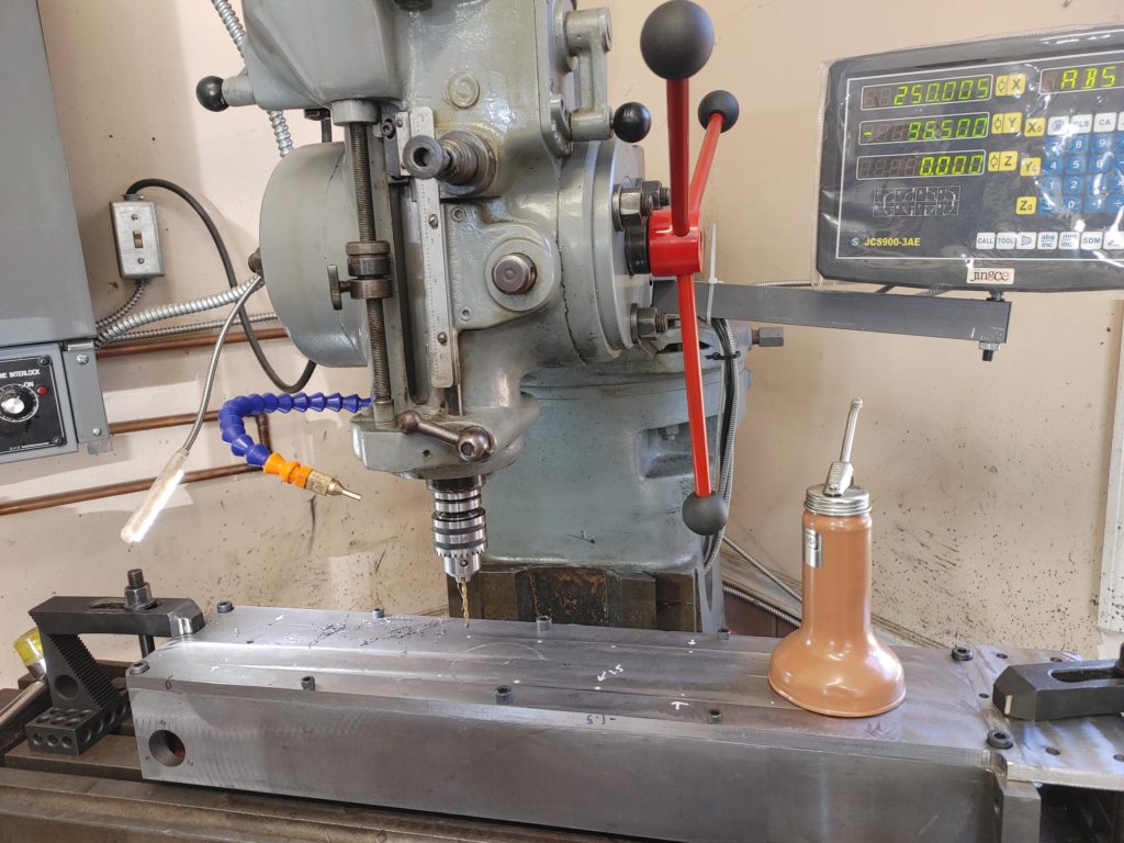
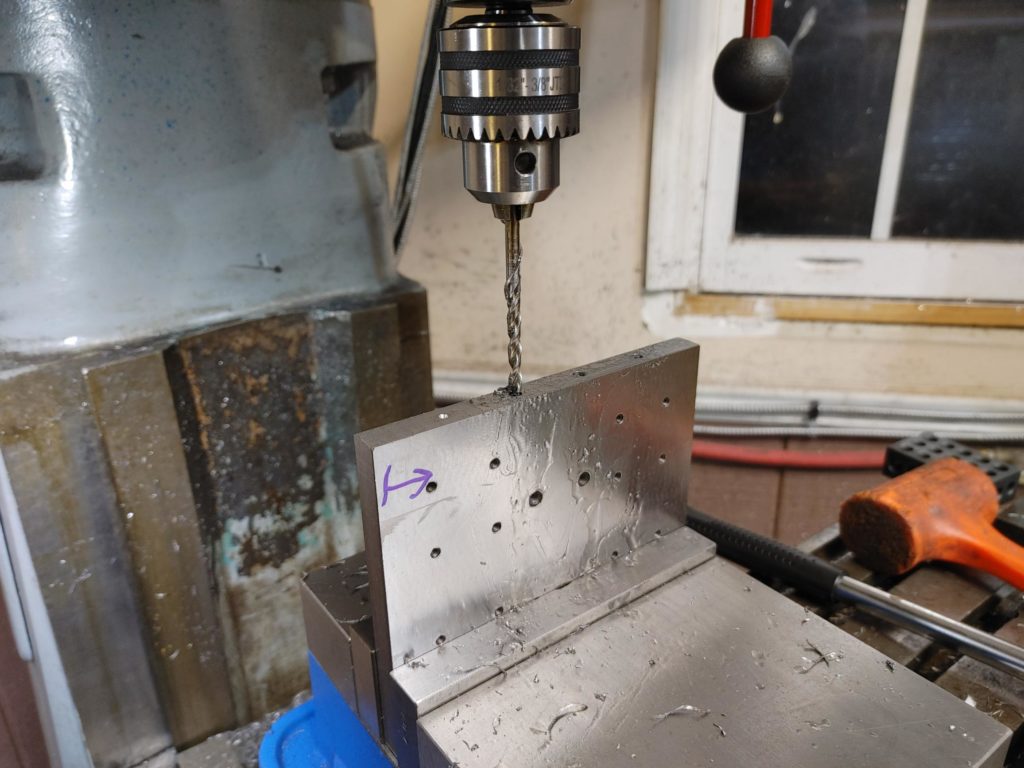
The next step essentially involved drilling a lot of through holes in the mounting plate. I used the mill DRO to ensure the spacing was correct for four 15mm trucks and the ball nut holder. There was no magic to laying this out – I just looked at the hole specifications for the linear rail kit I ordered and went from there.
Next I turned my attention to the column backing plate, drilling and tapping M6 holes to mount the linear rails.
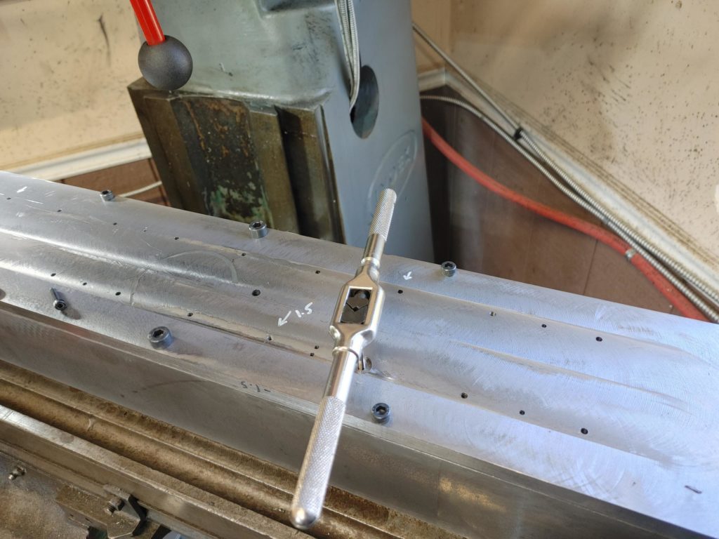
To help level the rails, I also drilled and tapped a series of M3 grub screws and then made sure they were all screwed in at a uniform height.
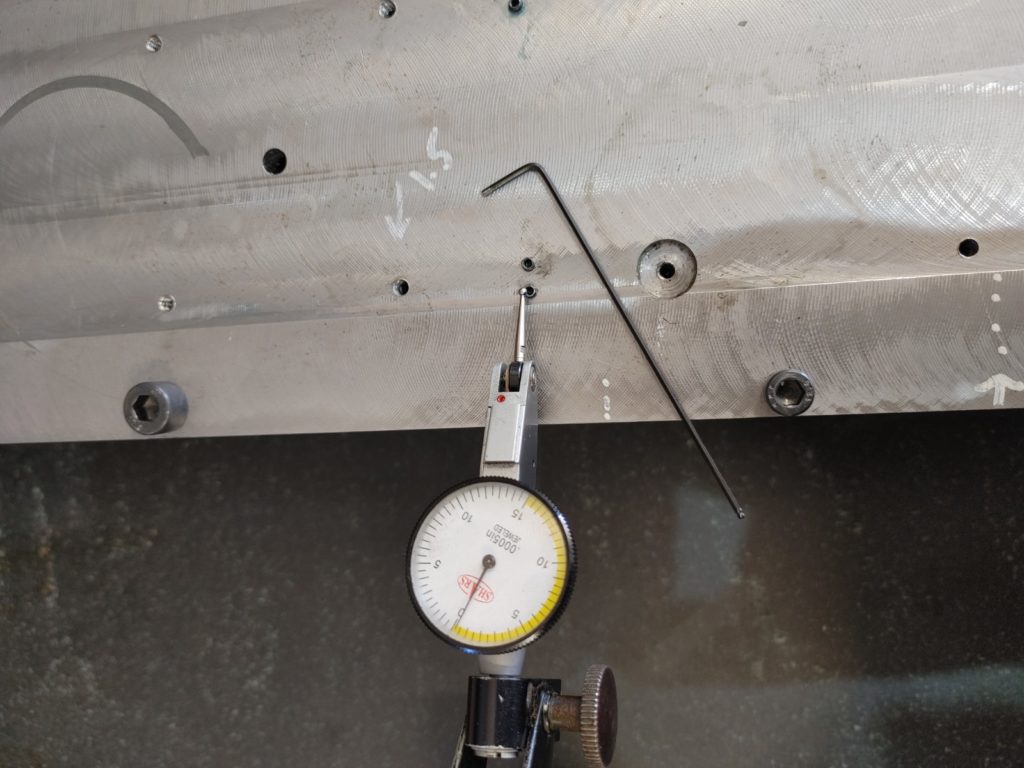
I then test fitted the rails. The ones I got were 15mm el cheapo specials from Ebay. One seemed a bit warped when I put it on the surface plate. But I’ve had good luck leveling things so far so everything should be all right. Right?
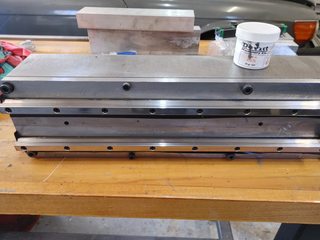
I struggled for a bit to get the rails level to one another but eventually wrestled them into submission (or so I thought). Parallelism was relatively easy to ensure by tapping the rails into alignment with one another using a small rubber mallet.
Finally, I fixed the rails to the rear column plate using machine epoxy. Here is where I made my first mistake. After an hour of the epoxy setting up, I tried to tighten down the rail mounting bolts a bit to put more pressure against the grub screws. This immediately threw the rails out of level to one another (no longer co-planar), with one rail (the warped one) springing up at the ends, and the other turning slightly concave in the center.
Again, I wrestled them back in alignment and went to bed. This was my second mistake. I assumed that the epoxy would set and hold them where they belonged, but when I came back in the morning they had moved on me such that there was 2-3 thou drift from one rail end to the other. I’ve decided to go ahead and finish the assembly and see if they bind. If they do, I may try to file off high spots on the rails where the ball bearings ride since I have nothing to lose at this point and the issue is only at the end of travel. If that fails (which I suspect it might if if comes to that) then out comes the blow torch and a new set of rails will be on order.
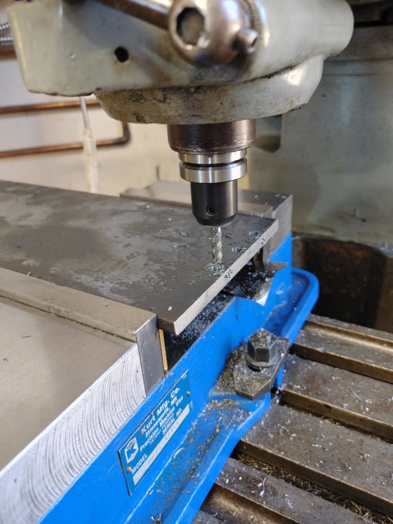
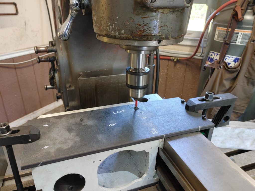
To complete the assembly, I next turned my attention to the two side pieces that tie the rear mounting plate to the head. I used 3/8″ thick, 6″ bar stock for these pieces. I left the stock at its 6″ mill width and rough cut it to length on a band saw. I then used the DRO and a small endmill to mill out 4 mounting slots at the end that connects to the sides of the rear mounting plate. It is important to use slots here instead of precisely sized holes to allow for play when initially tying the sides to the mounting plate and to allow for future wear.
Next I installed the head on the column, tightened it with the gib, and drilled mounting holes directly through both the side plates and the head casting to ensure they lined up perfectly.
Finally, I put a 45 degree chamfer on the leading edge of the side plates to trim them to length and match the 45 degree edge on the front of the head casting.
A coat of blue paint finished the plates. Then it was just a matter of assembling everything. First fixing the mounting plate to the rail trucks …
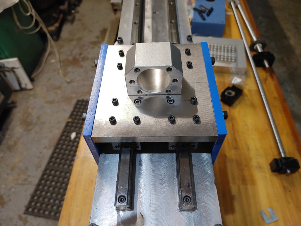
Then with the whole assembly.
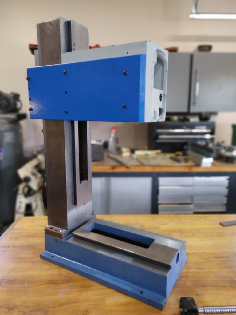
The result is a much heavier and rigid head. After doing some preliminary scraping I can tell that it wants to bind at the top of travel and that is keeping me from tightening the gib as tightly as I would like. But that said, the head is still traveling the full length of the column with no discernible play. I’d estimate the head assembly is now 40 pounds or so heavier than when I started.
A close examination of the gib shows that one side is not matching the angle of the column dovetail ways. I am going to scrape the sliding parts the rest of the way in and see where we are in terms of binding and go from there.
Overall, I’m happy with the design and the increased rigidity. Next up, we’ll complete the Z-axis ballscrew assembly.