Recall, the plan for the project is to substitute more rigid mill castings for the small X1 at the heart of the BenchMill 6000. At the same time, we want to keep the plumbing, software integration, and all the cool components of the Intelitek machine.
But what substitute castings to transplant?
This was surprisingly hard to figure out. A key design limitation for the project is the need for the new iron to actually fit in the BenchMill enclosure, which provides only 39″ x 28.5″ x 34″ of interior space to work with. On the small end of possibility, I immediately discarded the idea of using an X2 “mini mill”. It would certainly fit, but I would likely be swapping one set of rigidity issues for another.
I briefly flirted with the idea of building off of a Grizzly compound table, inspired by this excellent build thread.
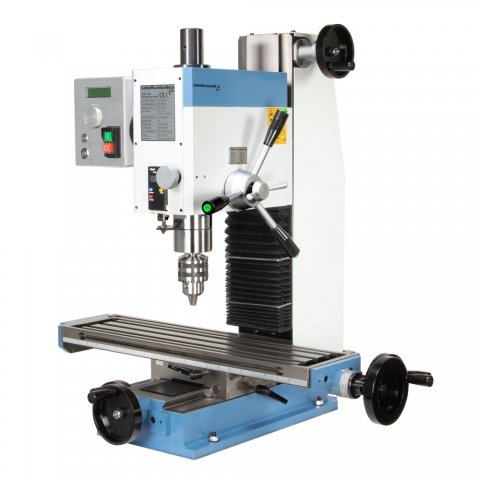
I eventually abandoned that idea after reading mixed reports regarding the quality of the compound table castings and worry about ensuring a rigid column connection. That not working, I next looked into acquiring castings for a Sieg SX3 bench top mill:
The SX3 has a lot going for it, but two things dissuaded me from this route. First, and probably most importantly, I couldn’t find a reliable source of SX3 castings in the States and didn’t want to literally depend on the slow boat from China. Second, the overall dimensions of the SX3 (720 x 760 x 990mm – about 28.4″ x 30″ x 39″) were too big to fit in the BenchMill enclosure, particularly along the Y and Z axes. So once again, back to the drawing board.
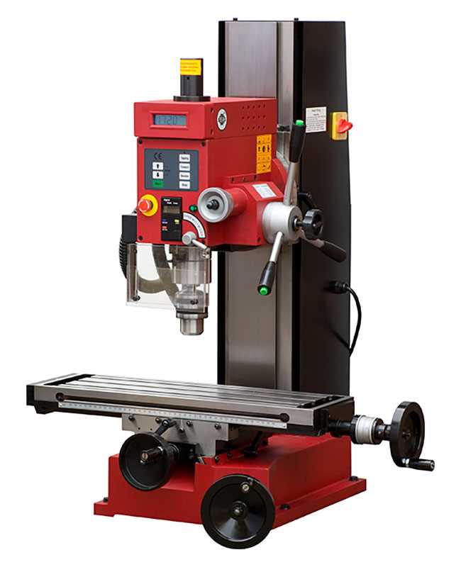
As most folks know, one of the best sources of spare Sieg parts in the U.S is the Little Machine Shop. Perusing their site, I noticed their HiTorque Bench Mill 6500 product, which indicates in its marketing material that it is based on a Sieg “SX2.7” frame.
Ah ha. Upon further research, it appears that the Sieg X2.7 uses similar castings to the SX3 except for the base, which features a lifting wheel in the SX3, and the back of the head, which includes a head tilting feature. With these features eliminated in the X2.7, the machine dimensions are cut down to 725x620x880mm (28.5″ x 24.5″ x 34.6″). This will allow for a much easier fit in the BenchMill enclosure. Some things may still need “persuading” but these dimensions are at least in the ballpark.
Despite this size difference, the X, Y, and Z axis travel of the X2.7 is nearly identical to that of the X3 and both come with an R8 spindle option. In theory, the X2.7 would feature only a 750W motor from the factory compared to the 1000W motor found on the X3, but I will be keeping the 1000W motor from the BenchMill, so power considerations are a wash.
After a couple of emails with the folks at LMS, I discovered that all of the castings were in stock and ordered a base, table, saddle, column, R8 spindle cartridge, and head casting. Along with a draw bar, gibs, and gib adjusting screws, the whole thing set me back another $1,500.
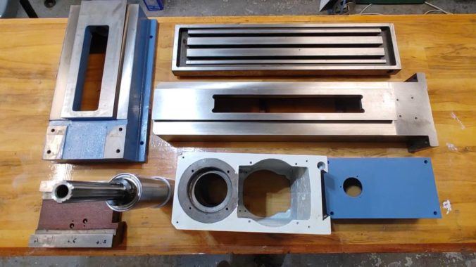
Shipping was prompt and, on receipt, I was reasonably impressed with the quality of the castings. Here is a quick breakdown of my initial impression:
COLUMN
The 2.7 column is open in the back with two reinforcing bars. This is to accommodate the design of both the X2.7 and SX3 where the Z-axis screw is internal to the column. While that may make for clean lines in an unenclosed machine, in my use case the open column creates a tremendous opportunity to further reinforce the machine by enclosing the back and tying it to the base, similar to the approach taken here. An epoxy granite fill may also be in the cards.
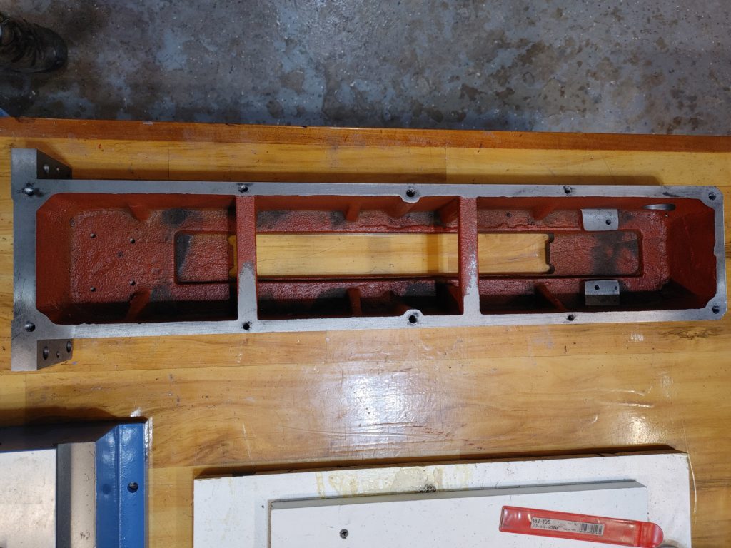
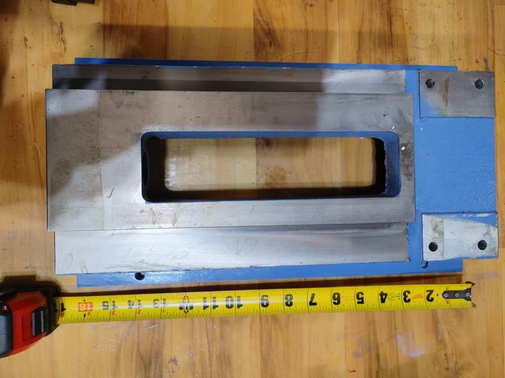
Even without modification, the column will be light years stiffer than the X1. It is about two inches wider, with thicker casting walls and a beefier flange for joining to the base. Here it is compared to the X1 column currently in the BenchMill:
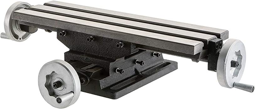
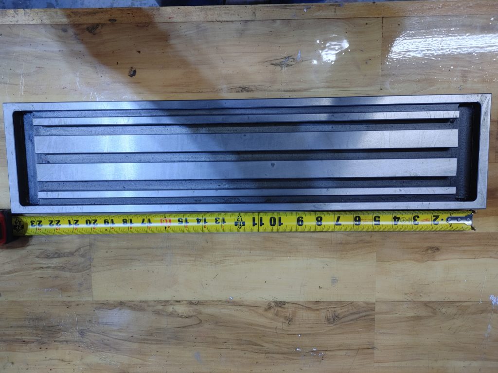
This appears to be similar to the table used in the X3. While it is much wider than the X1 currently in the BenchMill, the latter sticks its stepper motor out along the X axis. If I instead fold the X-axis stepper to the side of the new table in a 180 degree configuration, I should not lose much travel.
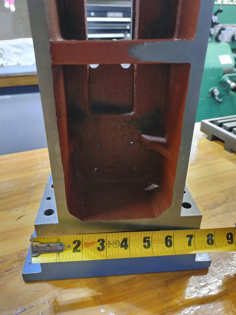
The base fits perfectly on the steel plate currently sitting at the bottom of the BenchMill, which leads me to believe a configuration using these castings was at one point considered by Sieg when designing the enclosure.
Importantly, there appears to be plenty of “meat” in the rear of the casting into which to tap mounting holes for the column reinforcing plate. More on this to come.
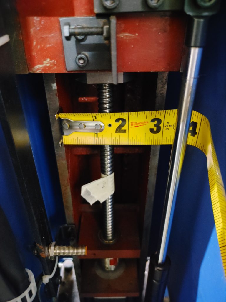
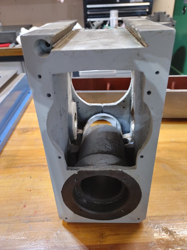
I was less impressed with the head casting. It makes sense to have a cavity so as to not have it be so heavy as to create column flex, and the design used here encloses the spindle motor within the head. I might normally quibble with the latter, but it is a critical feature here if I want this all to fit in the BenchMill enclosure. Nevertheless, the head clearly strikes me as the weakest link in terms of rigidity.
Overcoming this will be one of the design considerations moving forward. More on this is also to come.
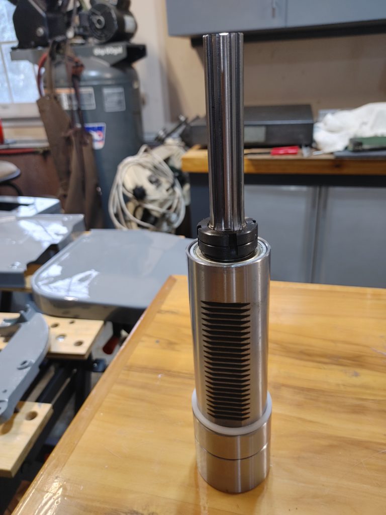
The spindle cartridge rotates smoothly, but doesn’t fit easily in the casting. I will probably have to take a die grinder to deburr the casting. Eventually, I will also need to turn a snap ring groove in the spindle shaft near the top in order to accommodate a “top hat” for the pneumatic draw bar control I will be adding.
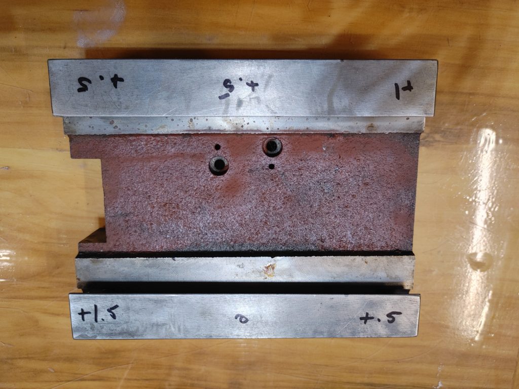
For the fun of it, I cleaned the shipping gunk off of the saddle and measured it for flatness on my surface plate. It was 1.5 thou out over a 5-6 inch distance. As a subsequent project, we will be grinding and hand scraping the saddle, as well as the base and table ways.
Overall, I am pleased with the choice of replacement iron. There is clearly work to do, particularly with the head, but the ingredients are here to produce a much more rigid bench top machine that takes advantage of all the built-in electronic bells and whistles of the BenchMill while delivering performance similar to more expensive commercial options.