Previously in our Benchmill CNC upgrade project we reinforced the Sieg 2.7 head casting and hand scraped the base. Now we’ll take our first steps toward adding CNC capability to the mill, starting with the Y-axis.
For ball screws we’ll be using a 360mm “C5” 1605 double nut model. I put the C5 accuracy designation in scare quotes because the ball screw I ordered was rolled, not ground, and most real C5 accuracy screws seem to be ground. Color me a bit skeptical. Still, the screw and nut that arrived were clearly of higher quality than the $30 Ebay specials one tends to see, and the nut/screw combination was significantly cheaper than a true ground C5 screw (at about $120).
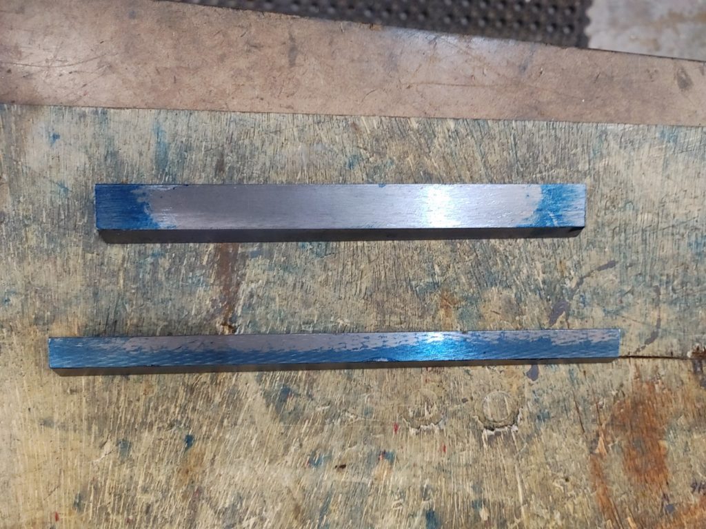
Before mounting the ball screw I checked Y-axis alignment and scraped in the Y-axis tapered gib. Bluing the gib on a surface plate showed that it was warped. Inserting the gib into the saddle tight enough to keep it from sliding also resulted in a fairly noticeable “rocking” in the saddle and with bluing indicated only an inch or two of the gib making contact. In other words, in addition to being warped, the angle of the gib doesn’t match the angle of the dovetail ways.
I’ve read complaints elsewhere about looseness in the saddles and heads of these import mini mills and after struggling with the head gib and now this one, I’m beginning to think that a lot of these problems stem from badly machined or warped gibs. They are made from steel and appear fairly springy: I’m not an expert, but I don’t see how they can be consistently manufactured without some degree of warping.
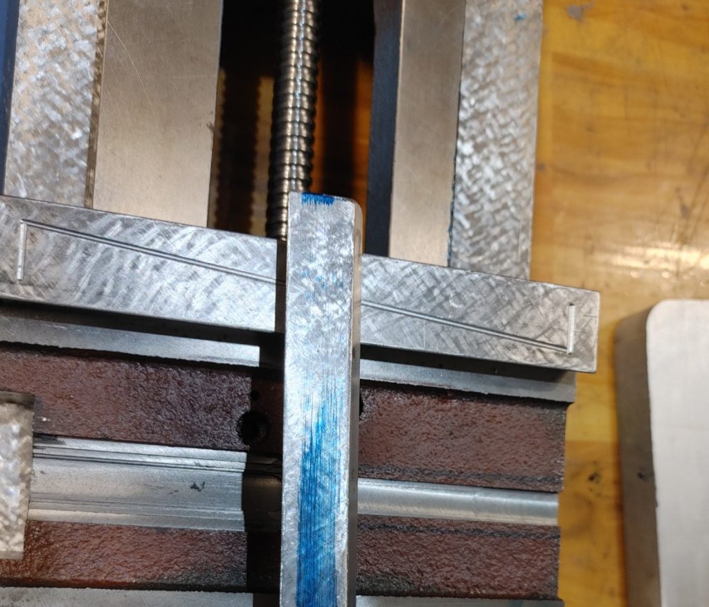
Either way, after a good 3-4 hours of scraping I was able to get the Y-axis gib relatively flat achieving contact across most of its length when tightened. During scraping I checked periodically for alignment using a Brown & Sharpe 20″ machinist’s straight edge held against two precision gauge pins in the top dovetail way of the saddle X-Axis (which becomes our X-axis reference). With some further scraping, we end up with good, tight contact, no rocking, and Y-axis movement perpendicular to the X-axis reference.
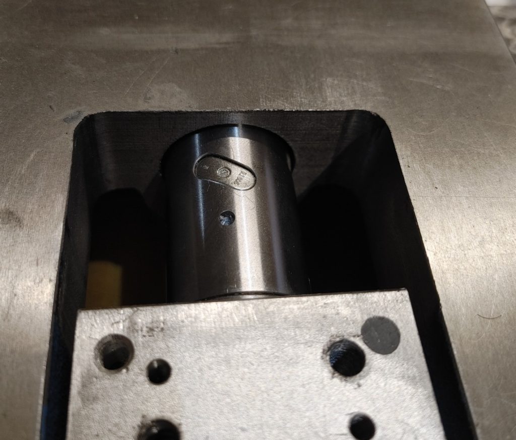
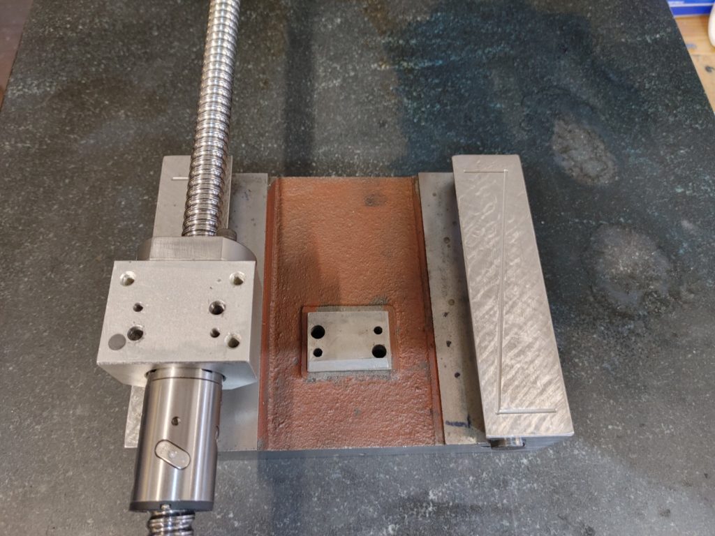
With contact and alignment good, we can now take a look at how the ball screw will fit in the base. As luck would have it, the hole at the front of the base is almost exactly wide enough for the double ball nut to fit in. This maximizes the travel and will allow us to get closer to the 8″ of Y-travel made possible by the spacing between the spindle center line and the column.
To maximize travel further, we’ll mill a 22mm (approximate — your mileage may vary) additional pocket for the ball screw mount at the front of the base, and a smaller pocket at the rear into which a bronze bushing can be epoxied to hold the other end of the screw steady.
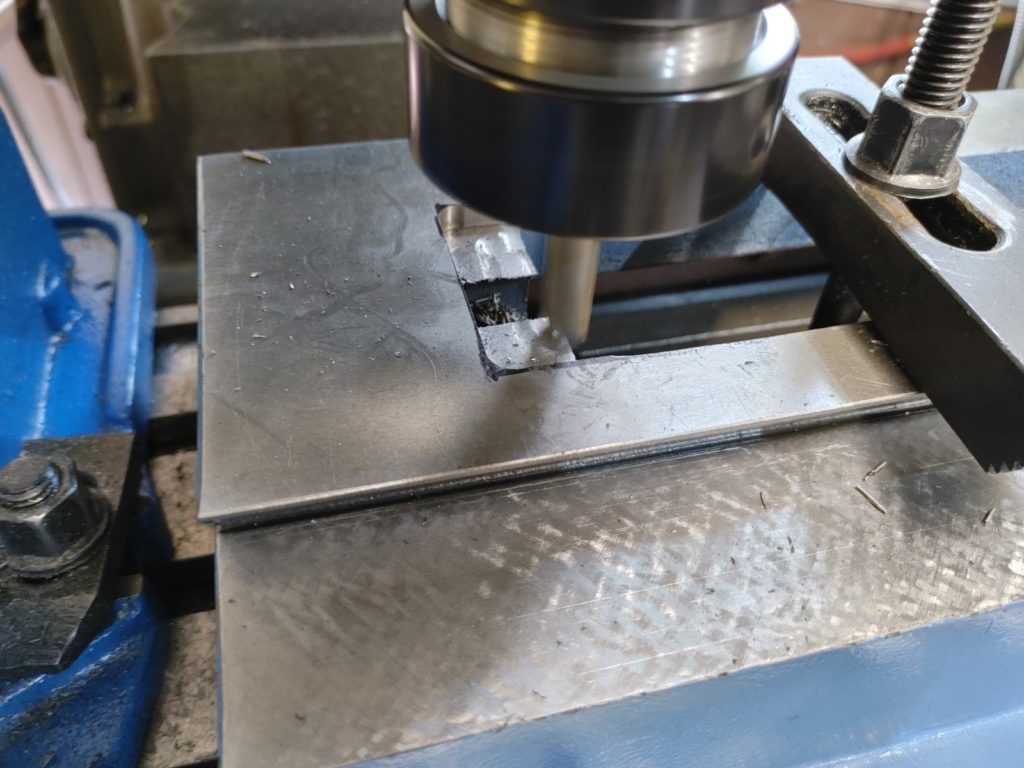
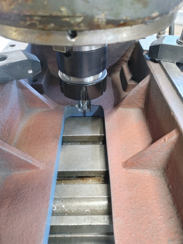
This will allow the ball screw mount attached to the bottom of the saddle to move further along the screw and give us close to 8″ of travel — considerably more than the 6.7″ travel advertised for a basic Sieg 2.7 mill. Once the pocket is milled, you can’t tell the difference.
The second advantage of this modification is that it allows us to mount thrust washers flush with the front of the base. As we’ll see in a second, this will allow us to use a single angular contact bearing in the front mount plate.
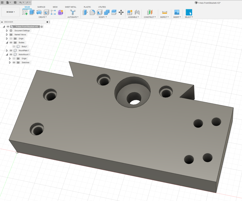
With thrust washers handling axial force toward the front, we only need a mounting plate that holds a single angular contact bearing to handle axial forces in the opposite direction as well as radial forces from the belt drive. For this I used an SKF 7201 (32mm OD, 12mm ID) angular contact bearing, which is plenty accurate for this application.
The mounting plate we’ll make needs to simply house this bearing and provide a mounting point for the motor mounting plate. I could have used any shape for the plate, but elected to mill a plate that covers the entire front of the base and matches its dovetail profile. This doesn’t need to match the profile perfectly and is more cosmetic than an actual dovetail extension, but I was pleased to see that the fit was good.
The motor mounting plate will attach to the right side of the base plate, and will allow the motor to be tucked under the right side of the table. A direct connection with the motor sticking out of the front of the base was out of the question for this application, since the 1605 ball screw being used here has a different pitch from the 1204 ball screw on the original Benchmill. We will use a 4:5 tooth count differential in our timing pulleys to correct this, allowing us to keep the original Benchmill 6000 controller and software while fitting the larger footprint into the Benchmill enclosure. A slot in the motor mounting plate will also allow a tensioning mechanism to be fitted.
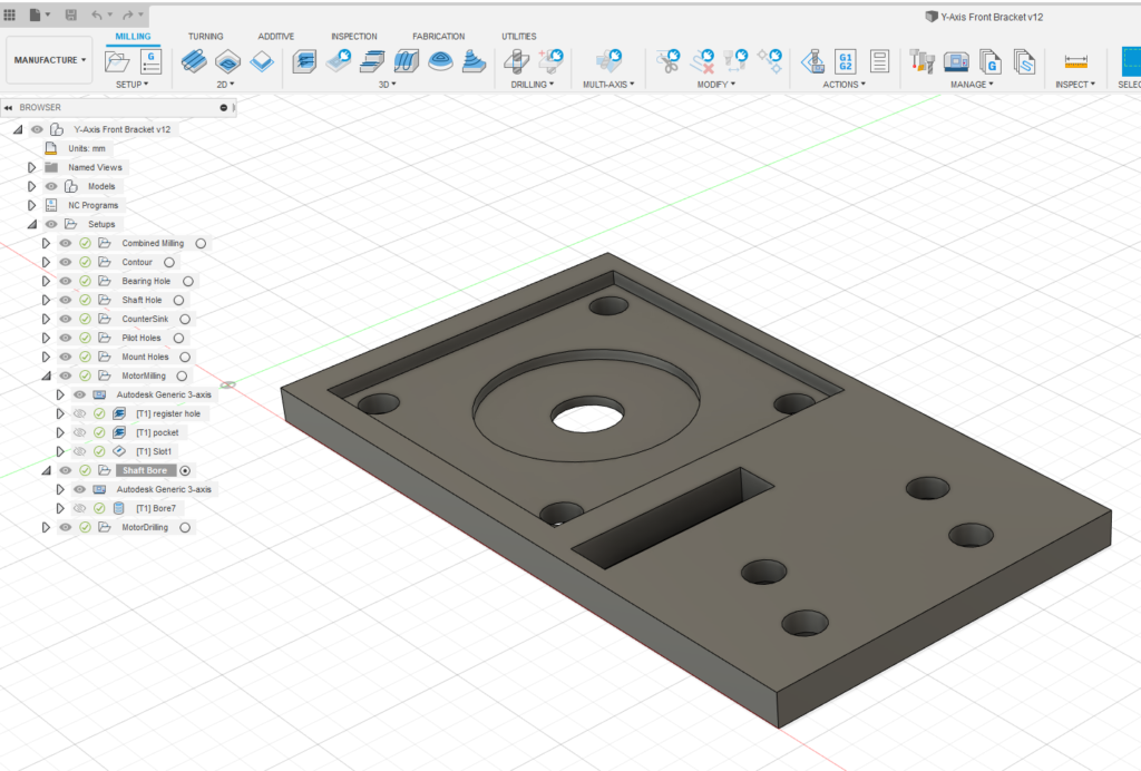
A this point, there is nothing for it but to mill the two mounting plates, first in the Benchmill (I still love how we’re using it to bootstrap its own improvement) and then on the Kearney & Trecker.
To make sure the motor pulley is in line with the ball screw pulley, we need to mill he motor plate out of 3/8″ steel. I wouldn’t want to cut steel much more aggressively than this on the little Benchmill, but it worked in the end.
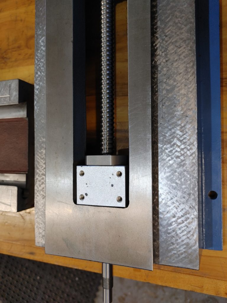
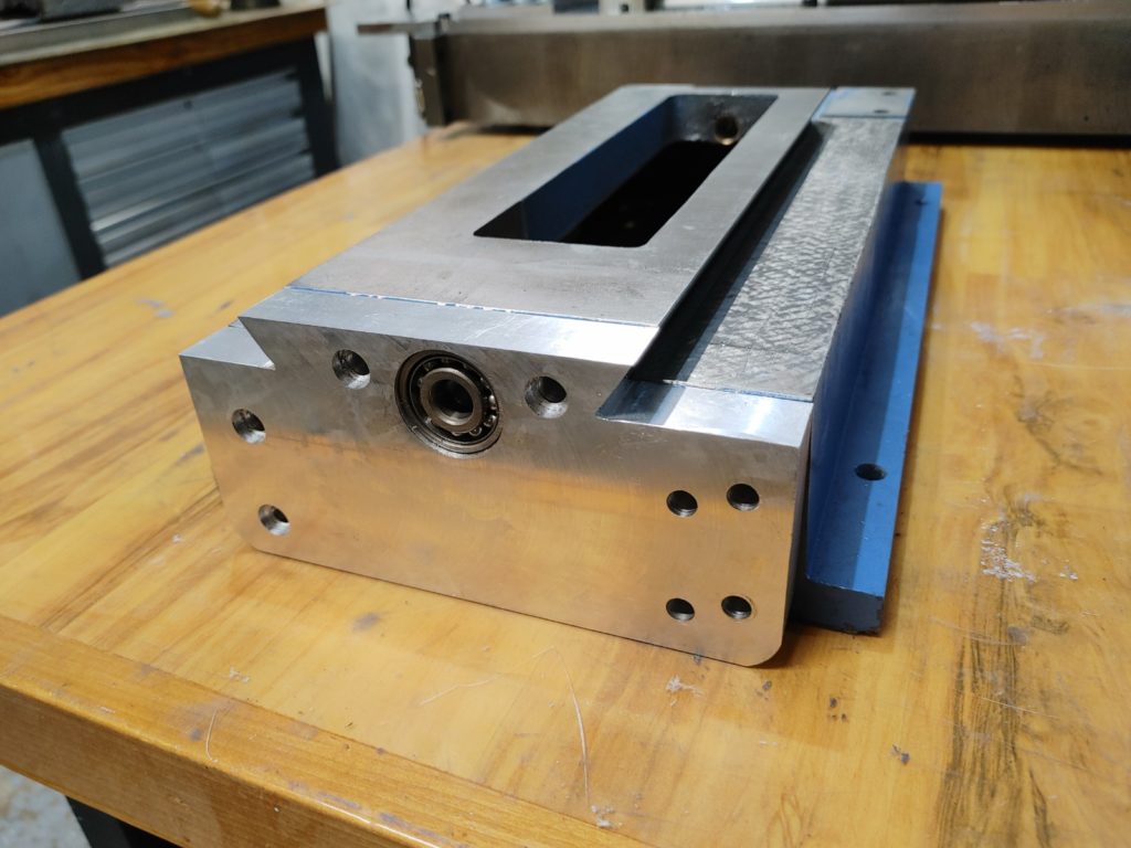
Here is the finished base mounting plate with the bearing inserted.
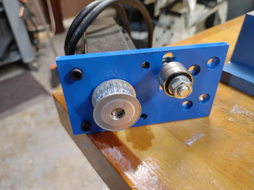
Here is the motor mounting plate, painted and fitted on the Nema 24 closed-loop (4nm) stepper motor we’ll be using for this application.
As a final step we need to attach the ball screw mount to the underside of the saddle. It is clearly no accident that the pad cast into the bottom of the saddle aligns perfectly with the top of the mount, height-wise. The only issue was that the through holes in the saddle don’t match the pre-drilled holes on the mount.
This was fixed by drilling and tapping two M6 and two M4 holes to match the ones in the saddle. One of the original holes in the ball screw mount was too close for comfort to the new hole, so it was filled with epoxy.
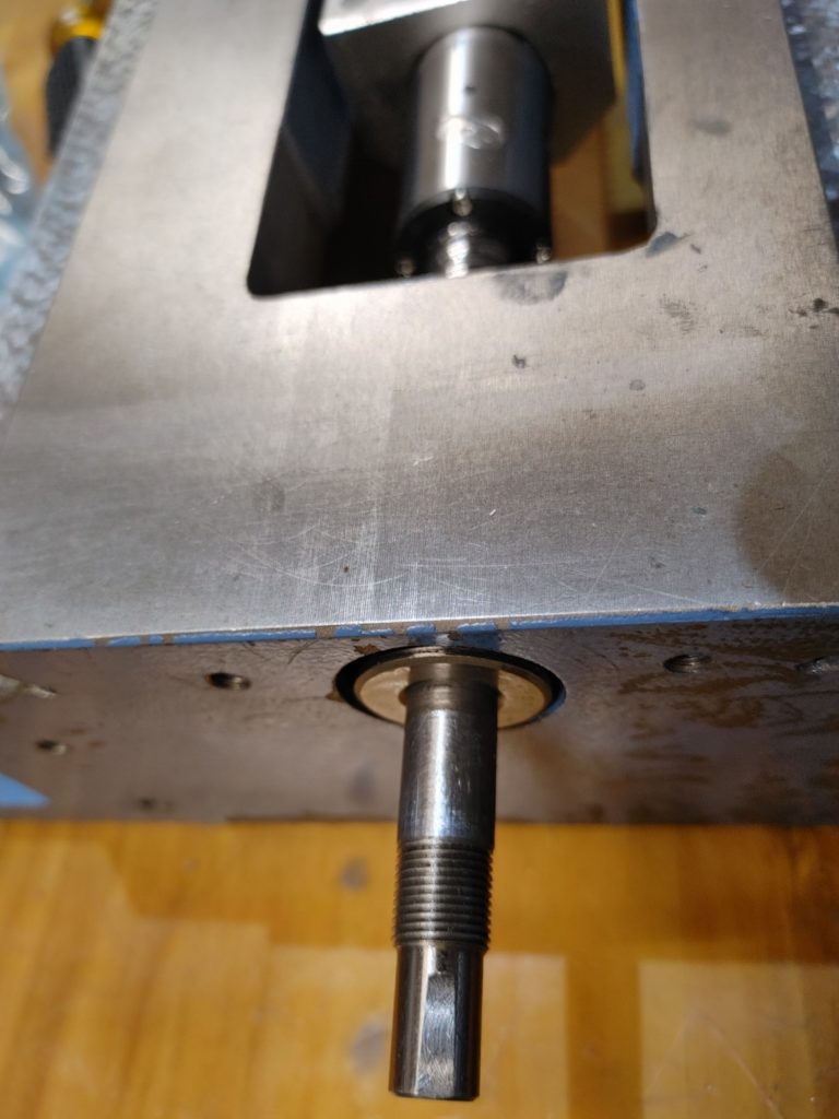
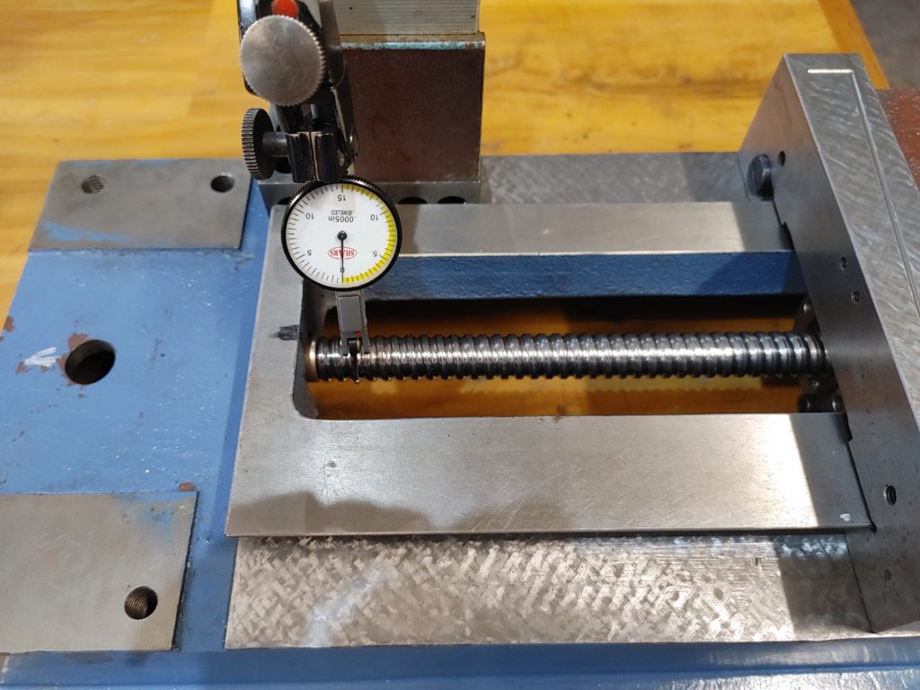
Here we are mounting it up, checking for alignment vertically and laterally. You’ll note the bronze bushing fitted to the end of the screw. This was later epoxied into the pocket milled into the base once we confirmed that alignment was good.
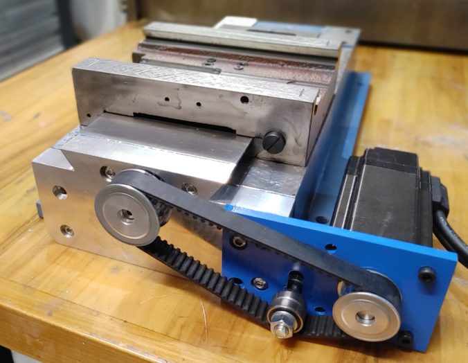
With final alignment verified, everything was fitted up. A 5M 25 tooth timing pulley is fitted to the ball screw and a 20 tooth pulley is fitted to the motor. A 415mm belt is then tensioned and we’re done. Here is he final result being tested using a power supply and cheap PWM pulse generator.
All in all, I’m satisfied with the outcome Next up, we’ll repeat the process with the X-axis.