Having successfully installed the CNC stepper motor mounts and ball screws for the Z-axis and Y-axis, it is time to finish with the X-axis. We’ll follow a similar design to the one we chose for the Y-axis, with an angular contact bearing held in a mounting plate attached to the left end of the mill table and a bracket tying the ball nut to the saddle.
The stepper motor will be mounted in reverse configuration using a steel mounting plate, tucked under the front of the table, and will turn the ball screw using a belt to achieve the 4:5 gearing ratio we need to use the Benchmill software with the new 1605 ball screws (the original machine uses 1204 screws). Unlike the Y-axis, where we used a bronze bushing to hold the floating end, we’ll use a regular sealed ball bearing held in a mounting plate on the right side of the table.
The main (left side) mounting plate will be milled from aluminum, the motor mount and the ball screw mount will be milled from 3/8″ mild steel, and the floating end (right) bearing mount will be 3D printed using carbon fiber filament, which will save us time and will be plenty strong for the floating end of the ball screw.
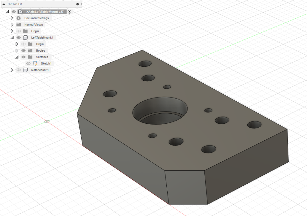
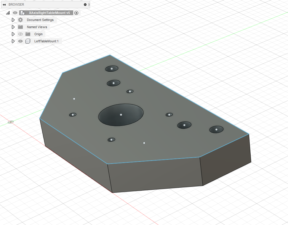
The left side mounting plate is a simple design, with a 32mm hole for the angular contact bearing (SKF 7201). A 12mm through hole will allow a thrust bearing (51101) to mount behind the plate and sit between the plate and the ball screw end. Four M6 bolts will secure he plate to the left side of the table, with the top two on the right side also securing the motor mounting plate.
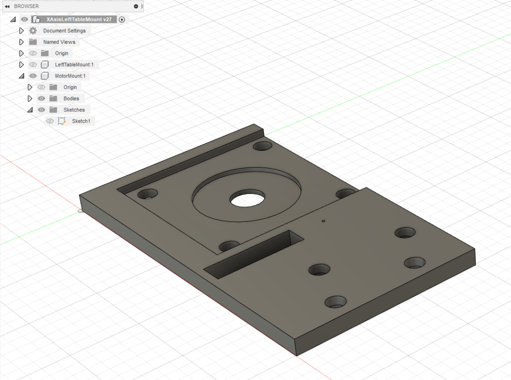
The stepper motor will be a Nema 24, 4Nm “semi-closed loop” model. To allow clearance for the motor shaft, the motor mounting plate will need to be thin, made from 3/8″ mild steel. As with the Y-axis, a slot will be milled in the plate for a tensioning bearing assembly (nothing fancy – two sealed wheel bearings riding on a bolt).
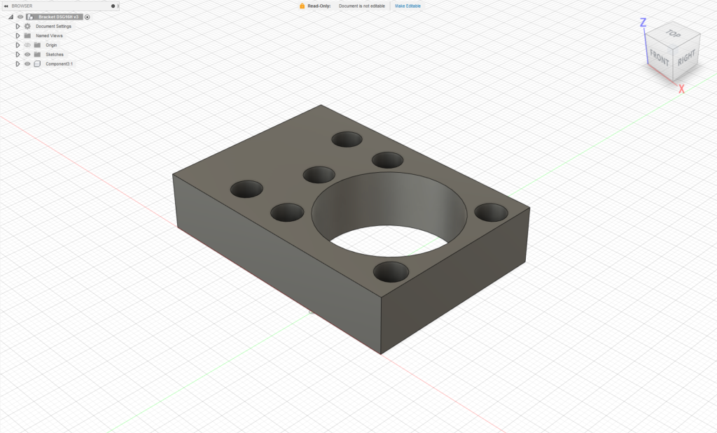
The ball nut mounting plate will attach to a cutout in the saddle, and is secured by 7 bolts (5 through the ball nut flange into the saddle and two only through the flange.
As mentioned, the right side mount is a simple 3D printed affair, with 4 screws and a hole to house the sealed bearing for the floating end of the ball screw.
Onward to manufacture. To make sure alignment worked, I first 3D printed the right side plate and motor mount, allowing fine adjustments prior to milling.
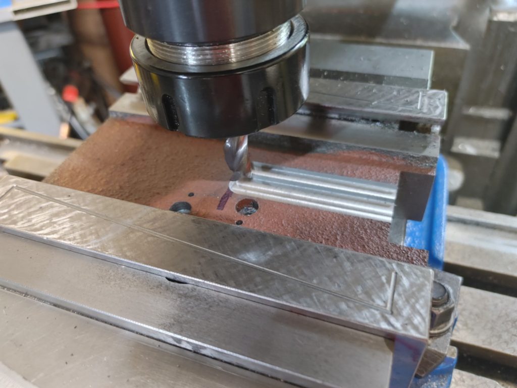
With the design tweaked, we can mill the plate on the existing Benchmill 6000, again using the old machine to bootstrap itself into something more capable.
The motor mounting plate and the mounting plate for the ball screw were both milled from mild steel bar stock.
Next, I dry fitted the saddle ball nut mounting bracket, which ended up needing to be shimmed by .002″ to ensure that the ball screw was level top to bottom. To get adequate clearance I had to mill away about 8mm from the top of the ball nut flange (not pictured).
I hated to do to it, but to provide clearance for the double ball nut, I also needed to mill a pocket in the underside of the saddle.
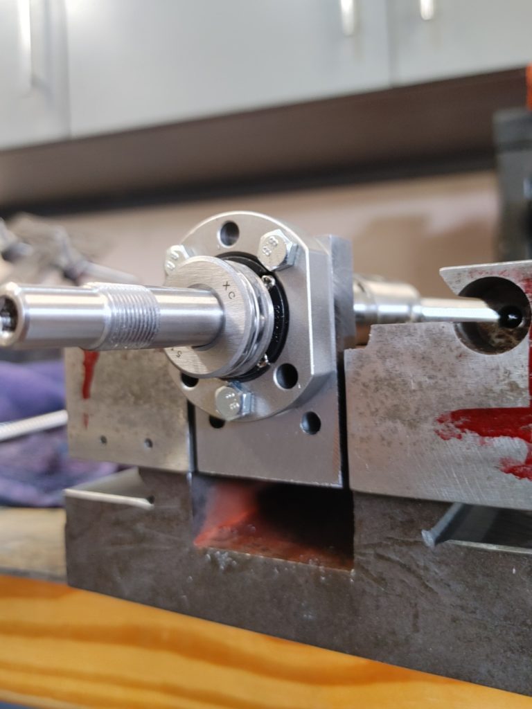
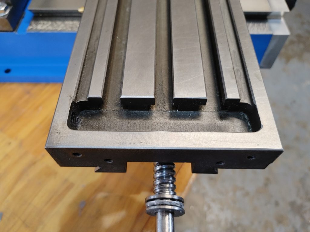
Next step was to drill and tap 4 mounting holes on either end of the table, using the holes from the mounting plates as guides. Here is the left end, showing the thrust bearing installed.
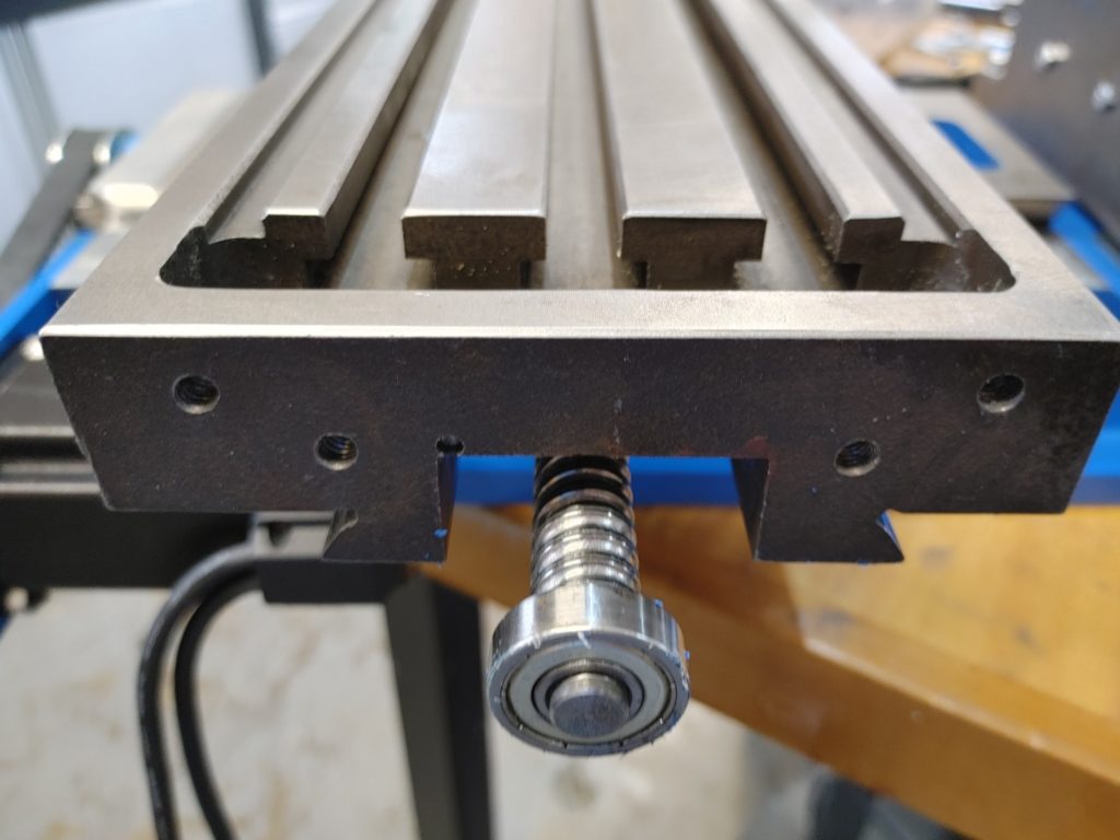
And here is the right (floating)end with the regular sealed ball bearing.
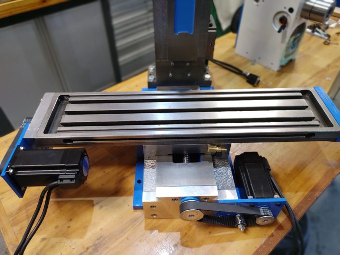
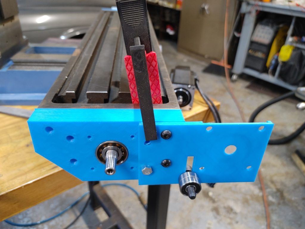
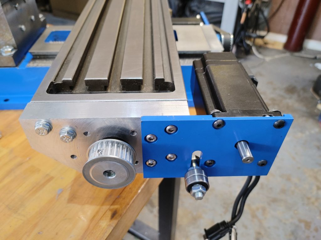
Then it was just a matter of installing the plates and making sure the ball screw was aligned properly – turning without binding at any point in the saddle’s travel. Here are the plates partially installed, with the stepper motor, tensioning bolt, and one drive pulley already mounted.
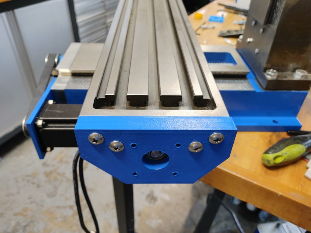
Here is the right side – the carbon fiber 3D print turned out fine and is exceedingly strong. Again, this end won’t see any significant force, either axially or radially. A 3D printed dust cap will screw over the end.
With everything tightened down, I tested the motion using a power supply and a cheap PWM signal generator (the HTD 5M belt I had on hand is way too loose – a tighter version is on order).
With that, we’ve completed the install of the CNC physical components. Next up, we’ll finish the head, cramming a 1.5KW servo motor into the head casting.