While we have the Kearney and Trecker feed gearbox out and the saddle off the mill, it is time to address the sorry state of the lubrication system. While we are at it, we’ll rectify two nasty surprises we’ve found inside and under the saddle.
Reapplying Turcite to Saddle Bottom
Recall, the y-axis woes of this machine can be traced back to Turcite (or some generic substitute) that had lost adhesion and allowed swarf to accumulate under the saddle ways. Upon removal of the old material (most of which I could do by hand) it looked as if there was not much work done to ensure that the bottom saddle ways were flat and co-planar before applying the original Turcite.
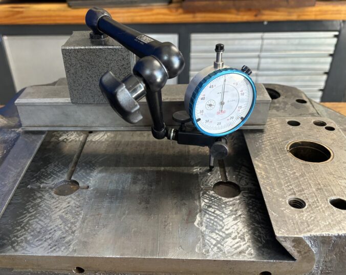
Using the bottom of the saddle as a reference surface, I was able to verify that there was indeed .004″ or so deviation across the ways. Rather than spend an eternity hand scraping them flat — and keeping in mind that this will be covered by new slideway material — I selectively deployed an extended pneumatic cutoff tool as a grinder, taking light horizontal cuts.
I know some scraping purists out there will come at me for this, but in my experience this approach can get you within .001″ or so of the final dimension and save LOADS of time. The fact that it leaves a nice rough finish for the epoxy is a bonus.
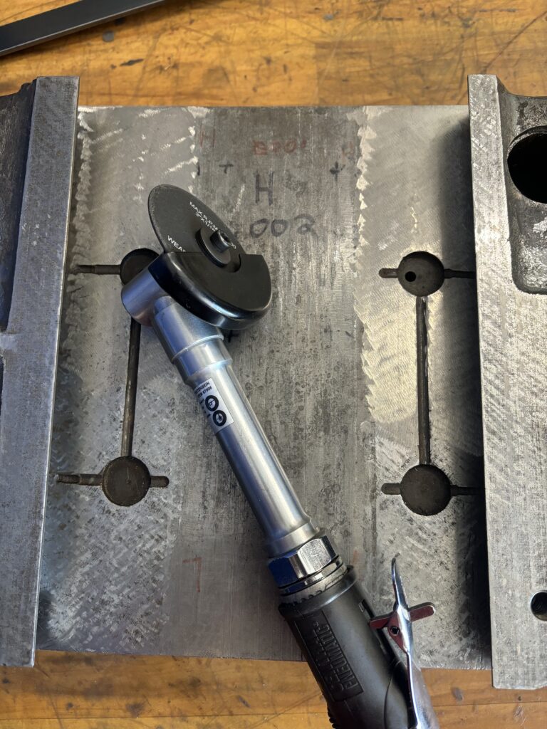
Anyhoo, after “grinding” the surface to within .001″ of flat, I turned to the trusty hand scraper to get it the rest of the way in.
To avoid a repeat of the delamination problem that had already plagued the machine, I cleaned the saddle bottom way surface with acetone and hit it briefly with a torch to sweat out any residual oil. I then applied the slideway epoxy with a grooved trowel and used my trapezoidal straight edge to hold the new slideway material down. After the epoxy began to set but before it was completely hard, I returned the saddle to the knee so the material could have a chance to conform to the scraped surface.
With the material set, I trimmed it, cut it away from the oil pockets, and epoxied in 3d printed cups designed to be flush with the slideway material (keeping it from peeling away). With the grinding work done already, I didn’t have to scrape very much to get it flat.
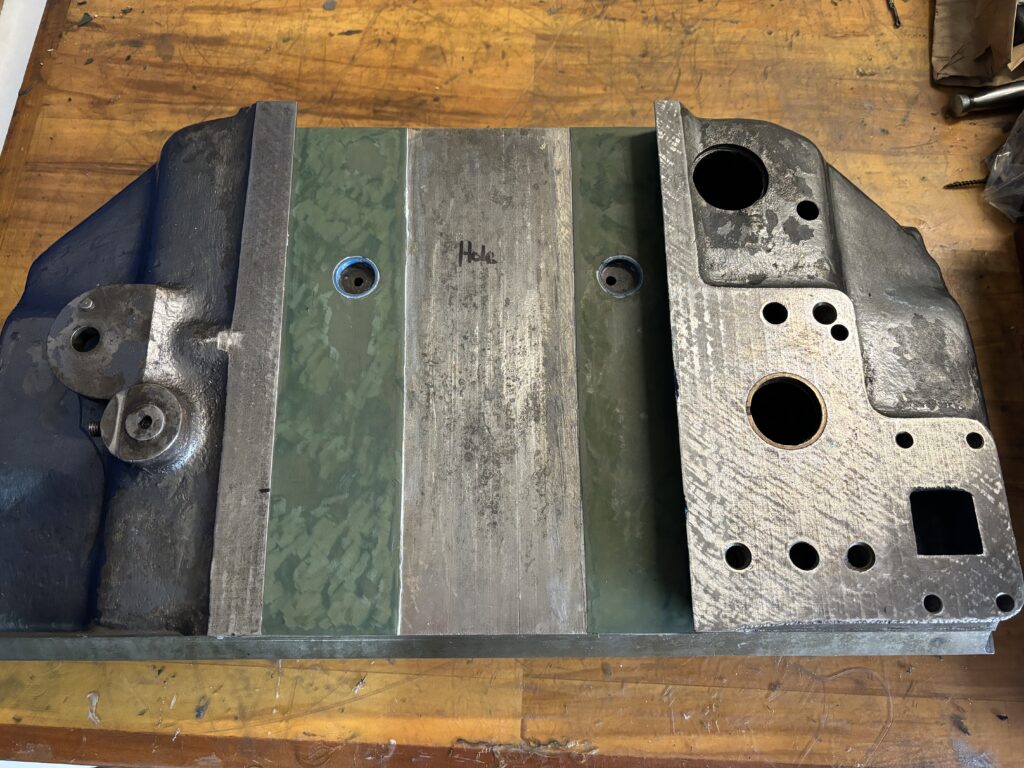
With this done, I ensured the dovetail ways were flat and used the saddle as a master to finish scraping the knee.
Repairing Broken Table Feed Selector Fork
The K&T uses a fork and lever system to select the x-axis table feed. When I first began disassembling the saddle, I was surprised to see that the bronze fork had broken in two. On close inspection, it looks as if this isn’t the first time this had happened, and may be related to the crash that stripped the tertiary high speed gear elsewhere in the feed gearbox.
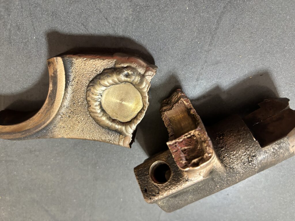
I had originally planned on TIG brazing the repair but found that if I cranked the heat up a bit the material would weld just fine. Before doing so, I made sure to gouge out around the crack so that the penetration would be sufficient.
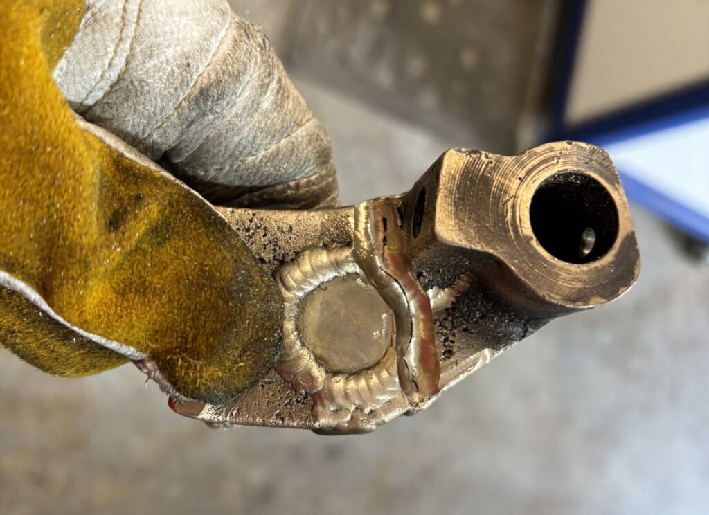
With the fork welded and re-installed, everything seemed to work fine. We’ll see if the repair holds, but I’m reasonably confident that it will as long as the machine is not abused.
Knee Lubrication
With the gearbox out of the mill, I had access to the oil sump at the bottom and back of the knee, which I had guessed would be overdue for a good cleaning. Turns out I guessed correctly given the quarter inch of viscous black goop that I found at the bottom of the sump.
That cleaned out, I turned to the oiling system itself. On the K&T, the gearbox lubrication depends on a small feed-shaft driven gear pump that sits on the right side of the knee. The pump draws oil from a pickup at the bottom of the sump and sends it through two copper pipes (well, one with a T-junction). These pipes have small holes poked in them that dribble the oil into the gearbox from above. Unsurprisingly, these holes were clogged.
For good measure, I began by pulling and cleaning the oil pump, lapping the case and gear faces on a surface plate.
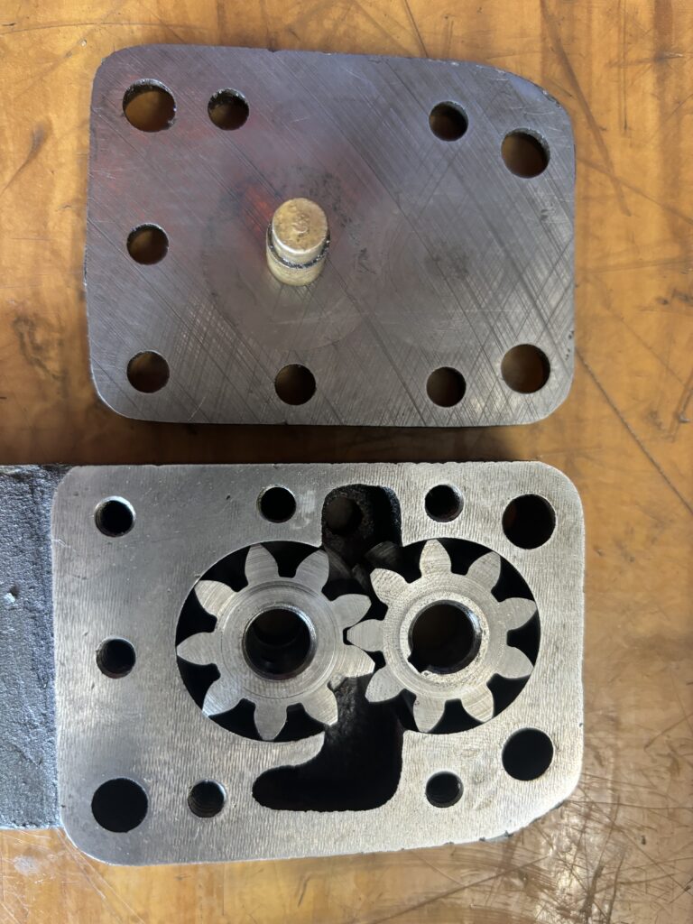
Next, I located the oil lines and cleared the tiny holes with compressed air and solvent. I also blew air back through the pickup tube to ensure it was clear.
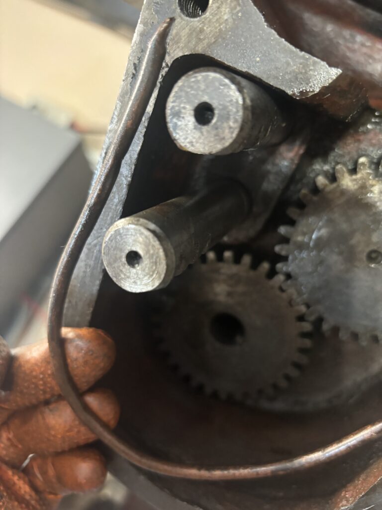

With everything reinstalled, I added a bit of oil and … voila … restored oil flow. (Well, mostly – I had to go back and work on one oil hole a bit more).
Saddle Oil Wick Replacement
The knee lubrication sorted, it was time to move on to the saddle. The K&Ts of this generation use a felt wick oiling system to ensure that the saddle ways receive oil. The wicks originate at a small reservoir at the front of the saddle, and are threaded through a series of passages to reach circular oil pockets at the top and bottom ways, as well as the feed selector shaft.
These wicks had long-since disintegrated on my machine. At one point, some enterprising machinist had attempted to use pipe cleaners as a replacement, which were a chore to fish out. I ended up using a piece of TIG wire bent into a hook to extract the pieces and fish out the gunk.
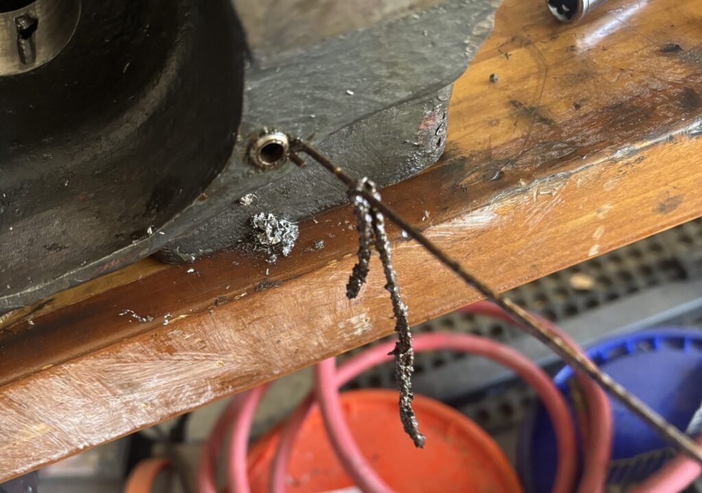
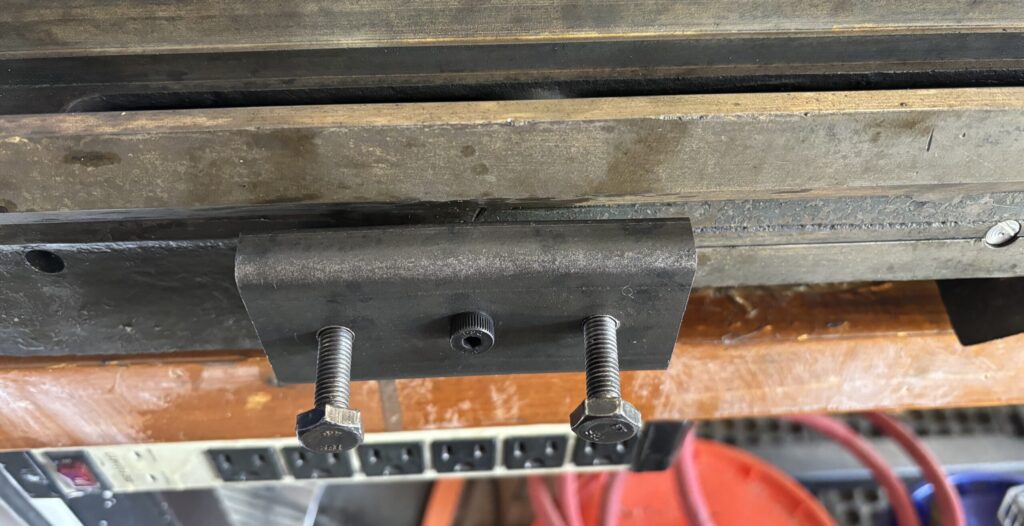
As a quick note: accessing the oil passages requires you to remove four 3/8″ plugs on the back and side of the saddle. I did this by drilling and tapping the plugs, then using a shop made puller to extract them.
Replacement felt wicking (“cord”) can still be bought from MCmaster. Installing the wicks requires the intrepid rebuilder to (as best I can tell) run them as follows: (1) one wick each to the top front oil pockets (servicing the front table x-axis way) then through a second hole in each pocket to reach the bottom way oil pockets on either side of the saddle (knee y-axis, left and right); (2) one wick each to the top back oil pockets (rear table way); and (3) a third wick to the oil hole for the feed selector shaft.
Youtuber My Lil’ Mule has a great video that perfectly captures the frustration of threading new felt wicks through the oil passageways without breaking them. My only advice to supplement his commentary is to avoid the temptation to use 3/16″ felt “because it will be stronger and harder to break”. On the contrary, it is a hair too large, and the friction of multiple wicks trying to occupy the same passageways invites breakage. Go with the 1/8″ felt.
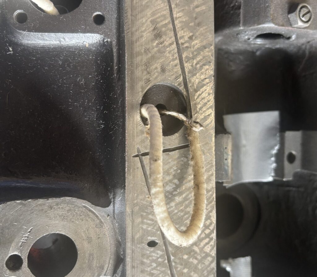
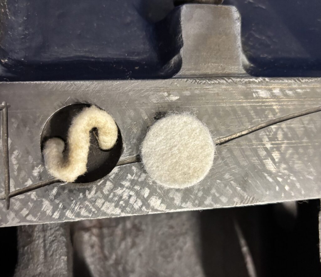
With the wicking pulled through all the passages, I punched out small 1″ felt pads to sit atop the cord within the oil pockets. Testing with a bit of oil in the reservoir, it took some time but after a day or two oil was being delivered to the top of the knee. We’ll call that improvement.
We’ll leave it there for now. Lots of work this month to basically fix wear and tear, as well as correct a bit of failed prior repair work. That said, we’re getting there.
Next up as the rebuild draws to its conclusion, we’ll report in on the progress scraping the top of the knee and the bottom of the table, the work on which is already well underway.
