From our initial diagnosis we know that our Kearney & Trecker (Milwaukee) 2HL Vertical mill has issues with power feed at any speed over 7 or so inches per minute. To figure out what is going on, we’ll need to remove the front of the knee and disassemble the feed distribution gearbox. I won’t go into too much detail since there is an excellent video already out there, but there are a couple of key points I can reinforce here.
Most of the preparatory work to remove the box requires work on the left side of the mill, where there is a small right angle feed change worm gearbox (#9 in the parts diagram below the fold). It is held in place with three slotted screws. Before removing it, best practice is to go ahead and set the feed to the lowest setting to simplify the feed timing when the feed distribution box is reinstalled (see discussion below).
Next, we’ll need to remove the trip dogs (#52) that ride on the vertical and cross feed rods (#55 & #53). These are each held on by a cap screw and slide off to the rear. In my case, some previous jackassery had resulted in one of the cap screws being positioned such that it rubbed on the underside of the saddle. I’m not sure if this was what was throwing off the Y-axis precision as the table was cranked out, but I’ll be keeping my eye on this possibility.

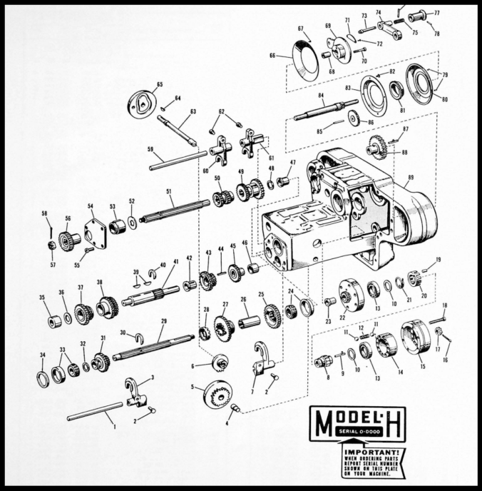
As noted, be sure to set the feed to the lowest speed. When reinstalling, we’ll set the gearing on the feed distribution box to the slowest speed, which will ensure we are in sync with the dial when everything is bolted back together.
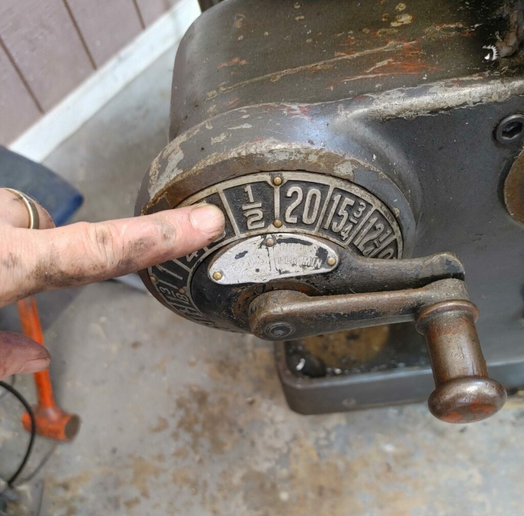
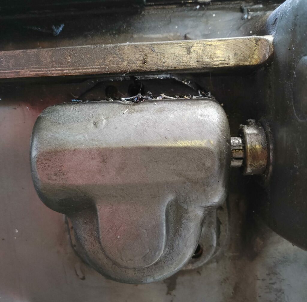
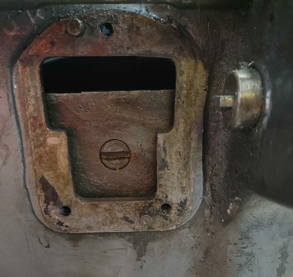
Here is the feed speed worm gearbox on the left side of the mill, before and after removal. The slotted shaft in the second photograph is actually the end of the feed change camshaft, which turns two cams to effect changes in the relative gearing, like an automotive transmission. If you look closely, there are actually two shafts, one inside the other. The slot is slightly offset to keep them aligned.
And here is a trip dog, looking from the front of the mill. Note the cap screw interfering with the saddle travel. It was significant enough to have worn a bright spot on the top of the screw. Hummm.
With the trip dogs and left side worm feed speed change gearbox removed, getting the feed distribution box off is just a matter of removing the half-dozen or so cap screws securing the box to the rest of the knee. At this stage, there really isn’t a need to remove anything else from the front of the knee, though you could if you wanted.
Safely Pulling the Front of the Knee
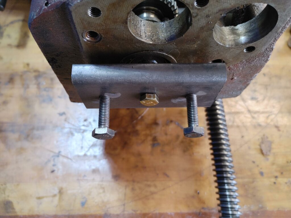
To make pulling the box easier, I threaded three pieces of 3/8 rod and secured them into several of the newly open holes to provide support as the (heavy!) feed distribution box is eased off the knee. I also bolted two hooks into the top two holes onto which I could hook a hoist.
Here is the feed distribution box with the cap screws out, the support rods in, and the two hooks in place.
To ease the feed distribution box off, I put a 4″ square tube to the back of the saddle, hooked up an engine hoist to the two hooks to support the knee, and used the Y-axis feed to push the feed distribution box out of the knee.
If I had this part to do all over again, I would have positioned my rigging differently, since the distribution box kept wanting to flip downwards as I removed it from the knee. That said, the engine hoist supported enough of the weight that I could control the movement of the box as I eased it off the knee.
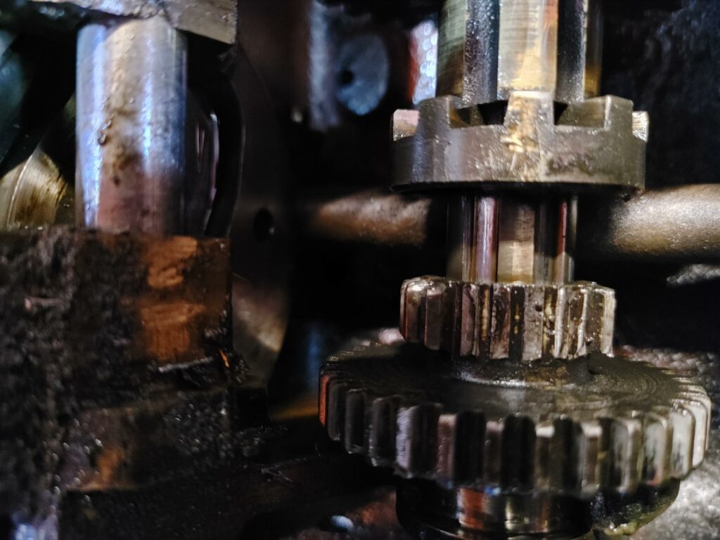
Once I got the box to the bench and flipped it over, I was able to inspect the two cams and the three shafts that make up the feed speed selection system.
It took about 5 minutes to spot why the feed wasn’t working at high speed. The “tertiary high speed cluster gear” (#31) had about half of its teeth stripped off!
Disassembly of Feed Selection Gearbox
The way the feed speed selection system works on these 2HL machines is slightly complicated, but not impossibly so. The feed change cam shaft (#63), whose slotted end is visible in the photograph above, turns a primary and a secondary feed change cam (#65 and #5). Four yokes (two on the tertiary shaft and two on the primary shaft) ride in groves in these cams, moving axially up and down the respective splined shafts to change the relative gear positions as the cams rotate. (Stay tuned and I’ll film this mechanism in action in a later post).
The important point here is that the relationship between these cams needs to be preserved when disassembling and reassembling the gearbox. This is partially accomplished by the slightly offset groove in the feed change cam shaft, but to be doubly sure I marked the respective positions of each cam in relation to one another and the gearbox casting prior to disassembly.
That done, the three shafts that have to come out are the “tertiary feed and slip clutch shaft” (#29), the “secondary pinion gear feed shaft” (#41), and the “primary feed shaft” (#51). To start this process, I began by removing the distribution box back plate (#54) and the hex nut on the primary feed shaft (#57).
For two of the three shafts, you’ll notice that there are two set screws at the bottom (top if it is flipped over) of the casting toward the back (you can see them in the first of the two photographs above. These hold bushings in place for the primary input shaft and the secondary pinion gear feed shaft. Loosen the set screws before removing the shafts.
If I’m recalling correctly, the primary feed shaft just pulled out from the back once the castellated hex nut (#57) was removed. For the other two, I rigged a puller using 3/8″ bolts to pull the shafts out. For the tertiary feed and slip clutch shaft, you’ll have to get to another castellated nut (#20) on the far side of the slip clutch (#22), accessible from the inside of the front of the casting.
With the shafts removed, I could finally get to the stripped tertiary high speed cluster gear, the small end of which is trashed beyond repair.
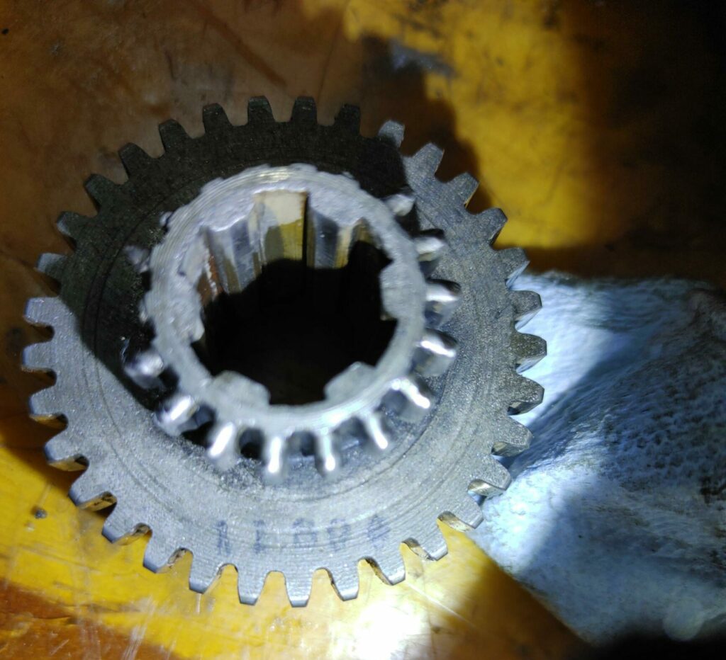
Not finding a cheap replacement for the cluster gear anywhere online, our strategy moving forward will be this: because the outer diameter of the small end of the gear is only 1.25″, I can just take a piece of .75″ ID splined sleeve bought online (OD of about 1.33″), turn it to size and cut a relief channel on my lathe.
I’ll then cut the 18 tooth gear from this blank on the CNC mini-mill. I’ll grind or cut the old stripped small end off of the old cluster gear and weld the replacement piece to the old large end of the old gear, using the splined shaft to keep both pieces in alignment. Because the gear wont see very much axial stress, a light TIG weld should be sufficient. I’ll then carbonize and case harden the repaired gear and reinstall.
Or at least that is the plan. Stay tuned and we’ll see if this works.