After upgrading the spindle and reinforcing the head of the Sieg 2.7 castings we are installing into our Benchmill 6000 CNC project, we can at long last turn our attention to the spindle motor. The original Benchmill sports a 1kW motor, but with servo prices dropping we’ll use this as an opportunity to upgrade our cutting power with a more capable motor to match our upgraded, more rigid platform.
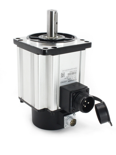
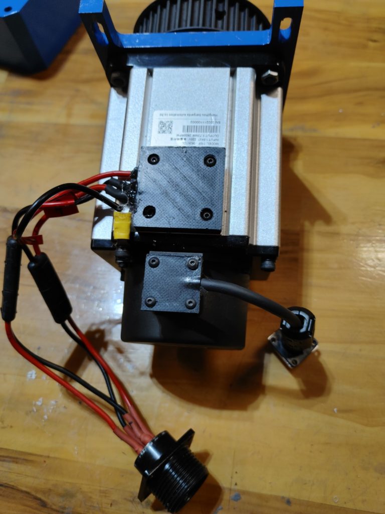
The motor we’ll be using is a Hangzhou Bergerda Nema 42 model (number 110F-0625TDL). It is a 1.5kW AC servo with a rated speed of 2,500 rpm and should be capable of delivering constant torque across that speed range. The Benchmill software is set up for a 5,000 max speed, so we’ll gear the motor at a 2:1 ratio using 40 and 20 tooth HTD 8M timing pulleys that take a beefy 25mm belt.
Our first challenge will be fitting the motor into the interior of the head casting. We could mount it upside down above the head as some designs do, but that configuration would interfere with the power drawbar we will be developing next and, in any event, would not fit into the Benchmill enclosure.
Fortunately, the dimensions of the Nema 42 frame fit, just barely, within the Sieg 2.7 head casting. To make that happen, we’ll need to first create clearance at the top of the casting and rearrange the wiring connectors of the motor so it can drop into the head cavity.
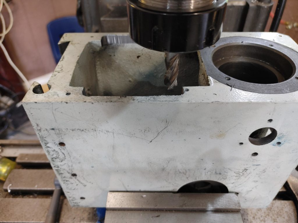
We’ll do this by carefully milling away the corners of the upper casting so the motor can be lowered into the gap. We’ll then drill and tap holes so a larger motor mounting plate can hold the motor in position at the top and keep it steady as it applies torque to the spindle.
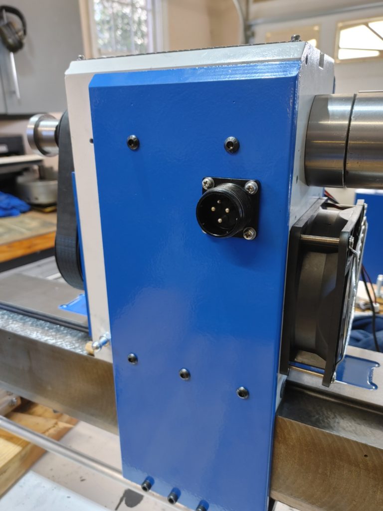
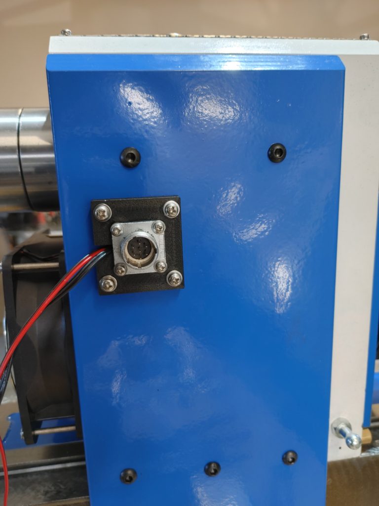
To create side clearance, I removed the bulky motor lead block, soldering the leads to two quick connect cables soldered, in turn, the the connection fitting for the motor power cable. A low profile 3D printed cover was then screwed over the old block, and hot glue was used to seal up the opening. The encoder connector cable received similar treatment.
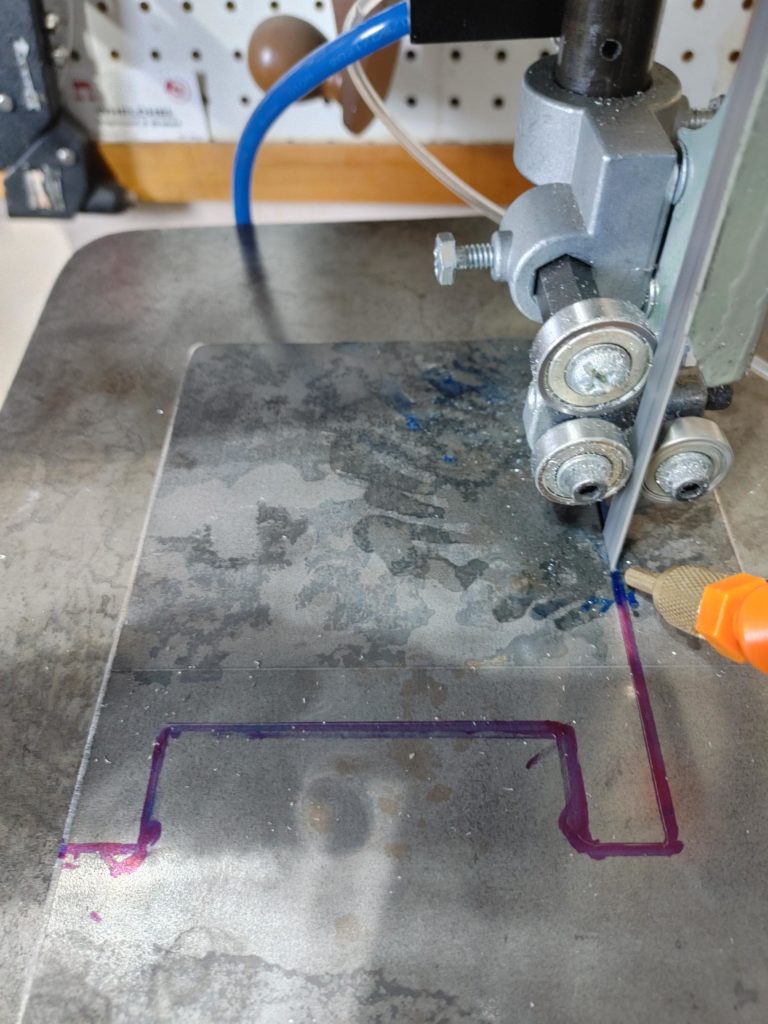
I then cut the motor mounting plate from 3/8 bar stock. The mounting holes, a through hole, and a Nema 42 sized motor register were milled into the plate using the old Benchmill (this marking he final operation of the old mill!).
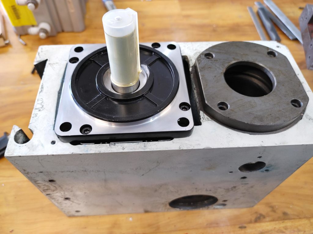
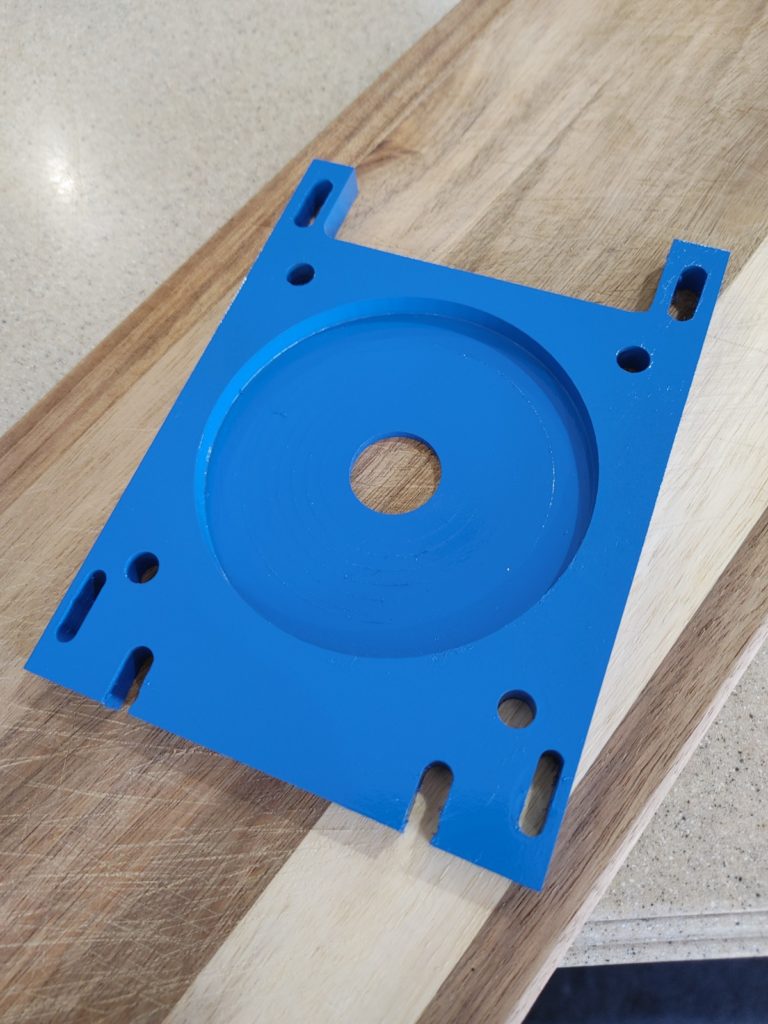
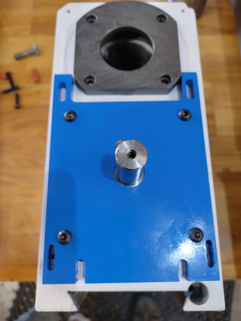
With a little blue paint, the mounting plate was complete. It attaches to the end of the servo, allowing it to hang down into the interior of the head casting while holding it steady. Slots cut for four M6 mounting screws allow it to be tensioned against the spindle to tighten the drive belt.
To allow the plate room for adjustment, I needed to mill off about a half inch of the bottom end of the spindle shaft upper bearing block.
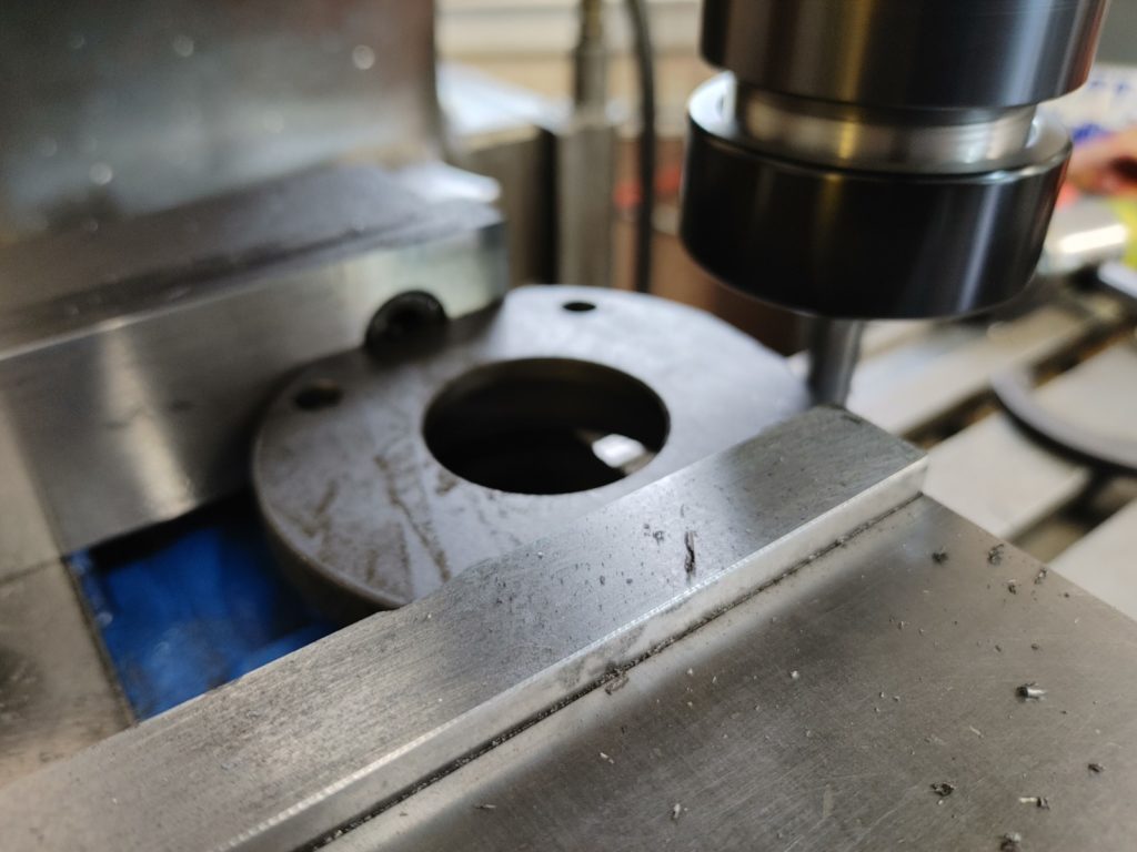
The upper spindle bearing block can be seen in position here. The block holds a sealed roller bearing that rides on the upper spindle shaft to keep it steady against the tension of the drive belt.
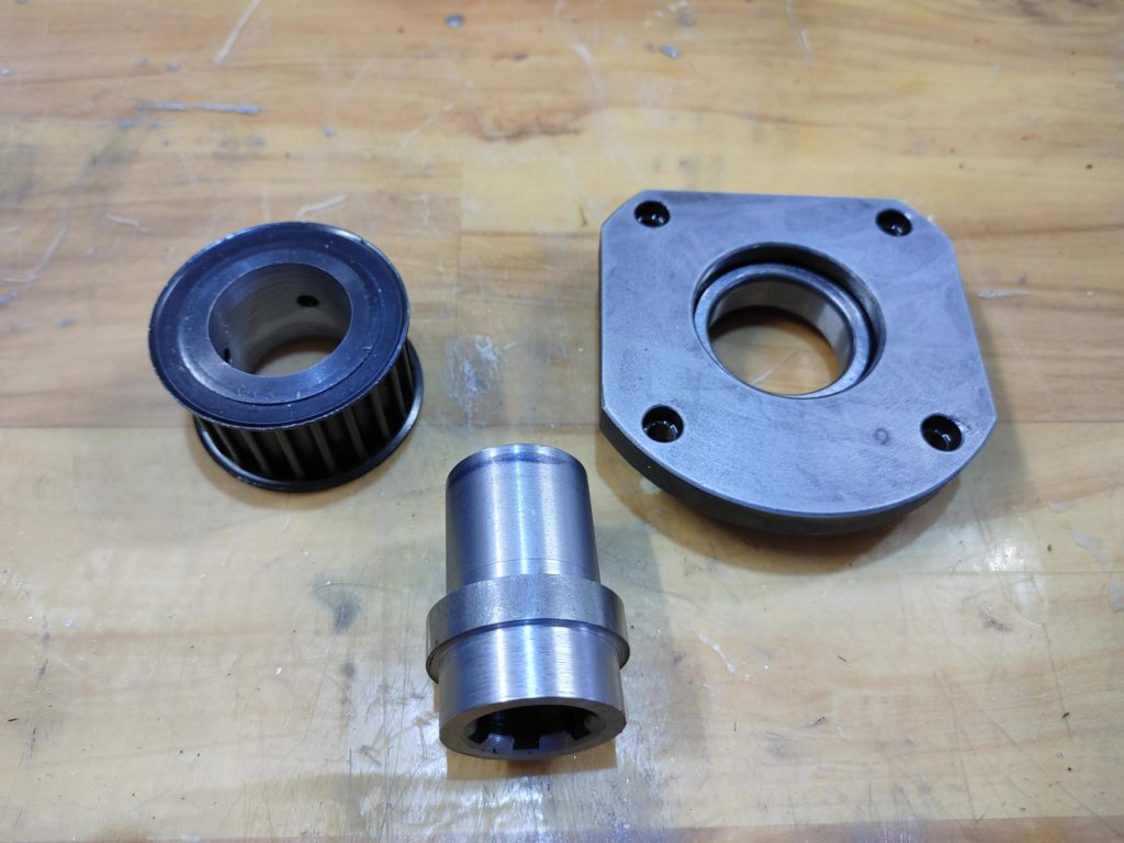
The next challenge was to find a way to mount the 20 tooth HTD drive pullley on the six spline upper spindle shaft so that it can be seated in the upper spindle bearing.
I started by boring out the inside of a 20T pulley and turning down a DIN 14, six spline sleeve to allow a press fit into the pulley. I turned the other end to just a bit over 32mm, to allow a second press fit into the inner race of the upper spindle shaft bearing (6007-2NSE9 part number).
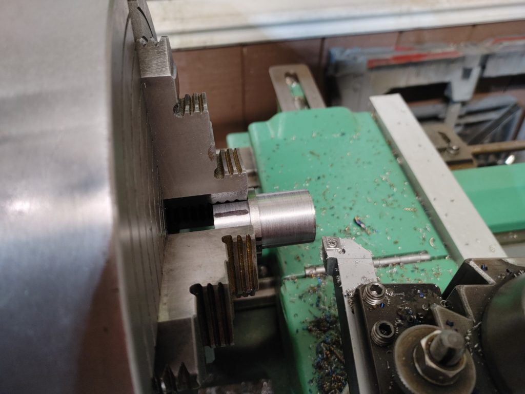
I have to confess that I screwed this part up my first try, failing to verify that the splines of the pulley were concentric to the pulley bore. I centered the part in my lathe based on the pulley bore and … ended up with a pulley that had 15 thousandths of runout. I ended up trashing that pulley, ordering another, and starting over after centering on the splines.
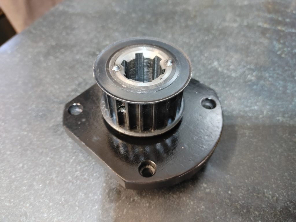
The second time was a charm, and I ended up with an assembly that fit snugly around the upper spindle shaft. I added a couple of light tack welds to make sure nothing slips.
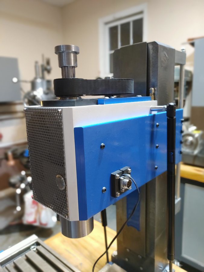
This done, I added holes in the side support pieces of the head, allowing me to mount the connectors for the motor power and encoder leads. A 3D printed adapter was used on the encoder side.
The wires currently coming from the bottom of the adapter plate go to a momentary switch mounted to the front of the head (to control the pneumatic power drawbar) and a 24v power lead for a cooling fan that will be mounted to the bottom of the head to draw cool air over the spindle and motor.
The final part of the project involved hooking the motor driver up to the Benchmill controller to verify that it can be controlled by the Benchmill’s Intelitek software. With a multimeter I verified that the Benchmill controller uses a 0-10v signal to command spindle speed. Fortunately, the servo driver I purchased has an analog input for operating in “velocity” mode that can be programmed to recognize a 0-10v signal.
Additionally, both the servo driver and the Benchmill are wired for NPN signals, with the Benchmill sporting a +24v common, with enable and direction connections switched to ground. The servo driver documentation indicated that it can accommodate a 12-24v common, but is sensitive to reversed polarity (my interpretation: you can burn it out by wiring it backwards).
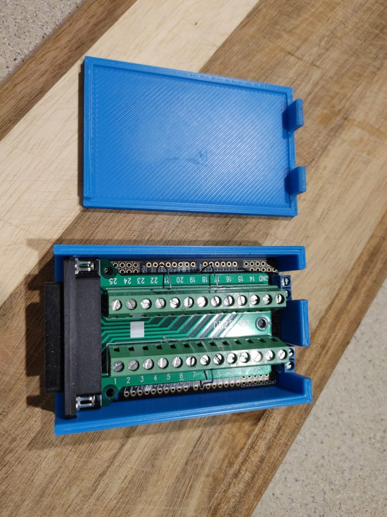
For piece of mind, a took a parallel port breakout board and wired inputs through a diode on the ground side and a 1k ohm resistor on the voltage common. The latter was probably unnecessary, but made me feel better since it created a slight voltage drop and in theory should add a small bit of protection against current spikes. A nice 3D printed box completed the component.
Programming the controller was relatively easy. I had to set acceleration ramp times and the PID loop parameters. I also needed to tell it which parallel port pins to listen to for “enable” and “direction” signals from the controller. Finally, I needed to scale the 0-10v input to the 0-2,500 rpm of the motor. With the 2:1 pulley ratio, this gave me the desired 0-5,000 rpm speed range needed to match the Benchmill software.
With that done, there was nothing left but to add a 464mm drive belt and fire it up to check for forward and reverse operation.
I won’t know for sure whether this was a success until I actually make some chips and verify the power. But for now, we’ll call it a successful upgrade to what is already becoming a capable small piece of equipment. Next up, adding a power drawbar to complete the head assembly.