Having initially scraped the saddle flat, the next step in converting our Sieg 2.7 mill castings into something actually accurate for the Benchmill 6000 CNC upgrade is to get the base casting flat and parallel to the bottom, and to make sure the base dovetail ways are flat and parallel to each other.
Throwing the casting on a surface plate showed that one corner was 7 thou (!) higher than the others. This is too much to attack comfortably using a hand scraper so I started by gently flattening the bottom of the casting with a die grinder turned at a 15 degree or so angle. Between rounds, I inked the bottom using Prussian Blue, just as one does with hand scraping, and checked on the surface plate between grinding rounds to make sure I headed in the right direction. When it was within 2 thou or so of being parallel to the top, I finished with a hand scraper.
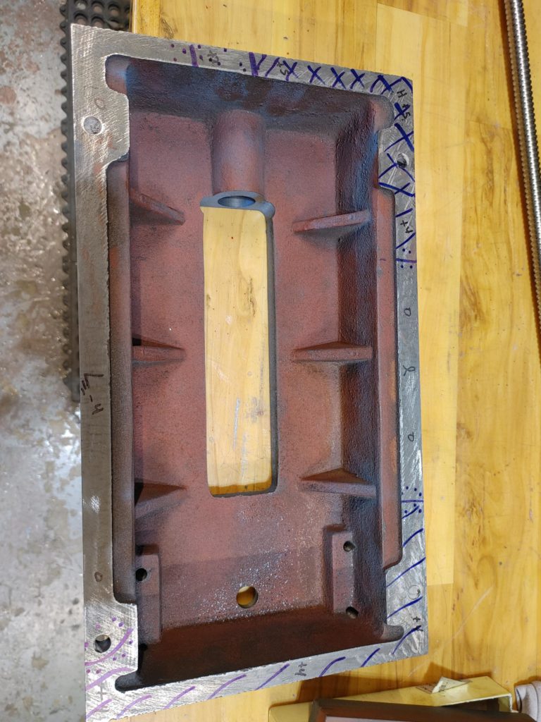
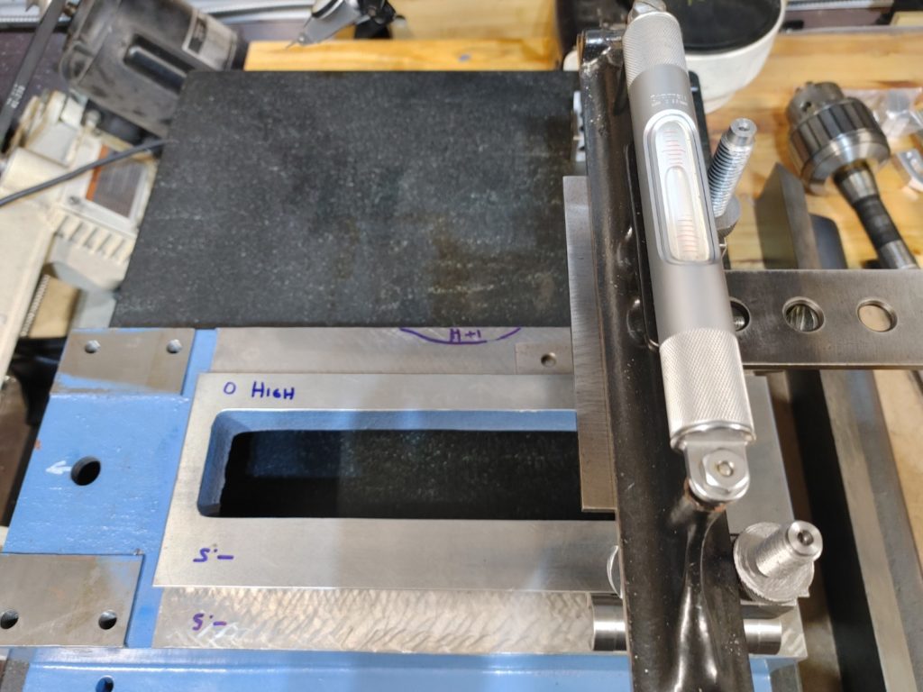
The high corner measured on the top corresponded to a high corner on the bottom of the casting, and after leveling the base the top was only out by about a thou over the 10 or so inches of its length (with a strange high spot in the center of one way that was out by another thou).

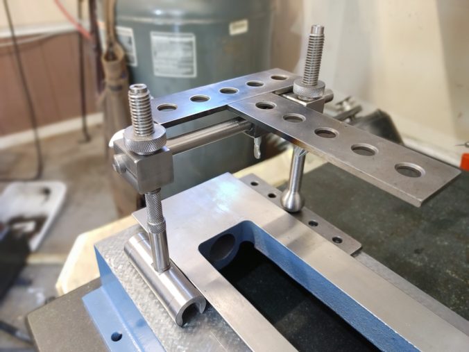
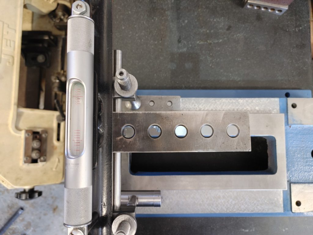
Checking whether the ways were co-planar using a shop-made King Way alignment tool and a precision level confirmed these readings (note the bubble).
This is what we’ll correct by hand scraping. I promised in a prior post to provide more details on how I hand scrape. I’m definitely not an expert (for that, search for Richard King), but in case it is helpful for anybody out there getting started, here is how I go about it.
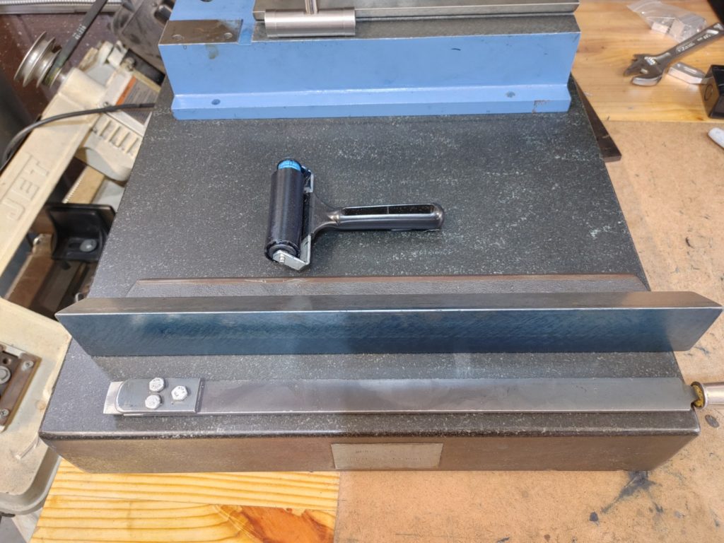
My main tool is a shop made scraper constructed from bar stock that holds carbide inserts. Depending on what is being scraped, I use either a granite surface plate or a section of a cast iron surface plate that I bought as surplus, cut, and scraped flat. It is perfect for a job like this as it has a dovetail edge ready to go.
My technique isn’t special — I ink the piece to be scraped using Prussian Blue and hinge it where possible to get a sense of high spots. I then scrape the high areas down at alternating 45 degree angles leaving room between scrape marks and the vertical rows. I’ll stone the surface flat to remove burrs between rounds.
This results in a checkerboard pattern (when I pull it off). Every three or four rounds, I check for flatness on the surface plate to measure progress and to make sure I’m not “scraping a hole”.
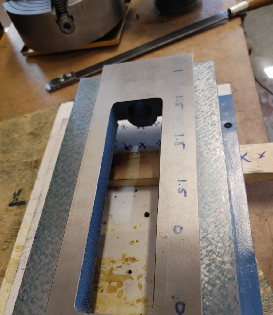
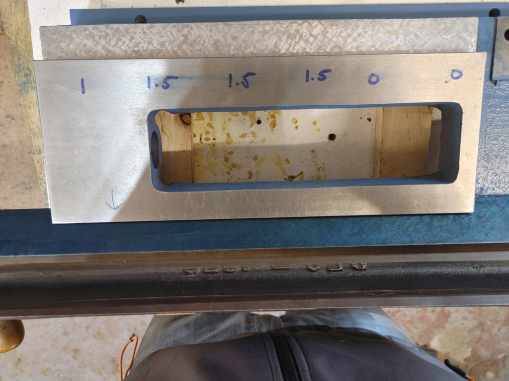
Where there is a lot of material to remove, I’ve followed advice to “step scrape”. To do this, zones are marked out and scraped down such that the highest zone is scraped first, then the next highest + the highest is scraped next (meaning the highest has now been scraped twice), etc. After, say, four rounds, the highest zone will have been scraped 4 times, the next highest 3 times, the next 2, and so forth.
I don’t tend to remove a whole lot of material each scraping round (if I am removing more than 1-2 tenth with a scrape mark I would be surprised).
After step scraping for five or so rounds from the perspective of the highest point, a picture begins to emerge.
10 or so more rounds, and we are getting flat.
I scraped to achieve a few more contact points on the ends, and then confirmed that we were indeed flat.
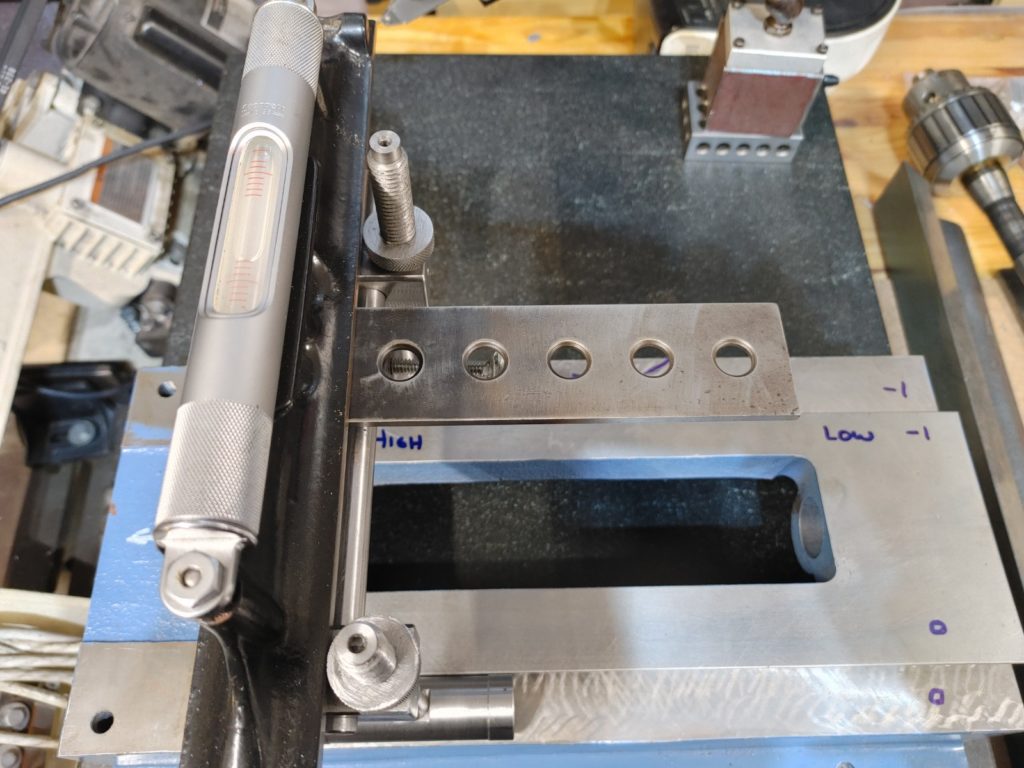
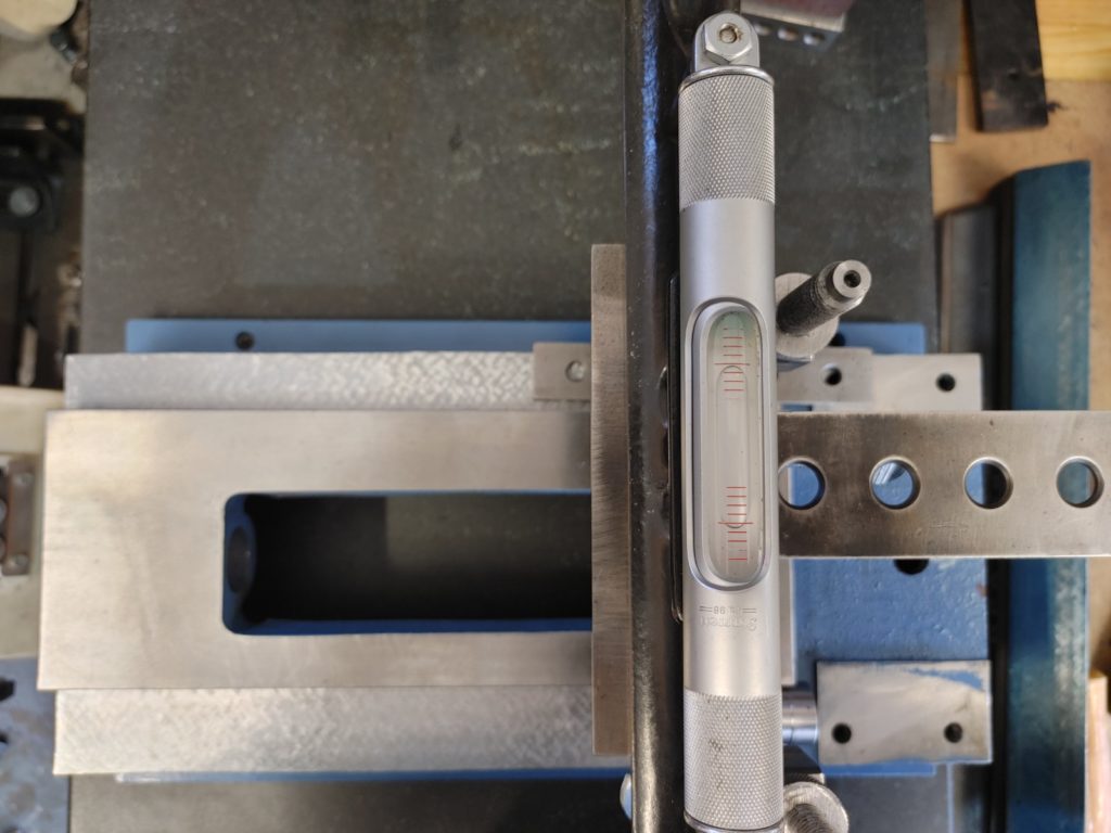
Checking with the King Way shows that we’ve made the ways co-planar. (Again, note the bubble – this is a Starrett machinist’s level with the original vial replaced with a much more sensitive version. A .001″ shim at one end moves the bubble from one end to the other — well over 8 graduations).
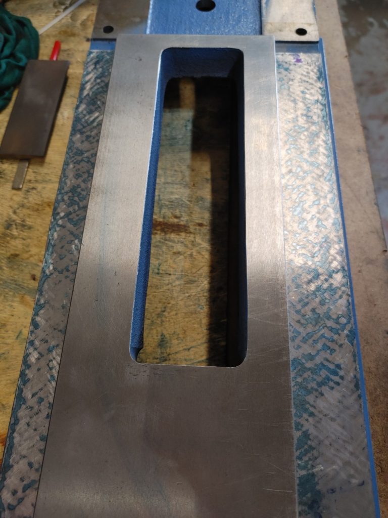
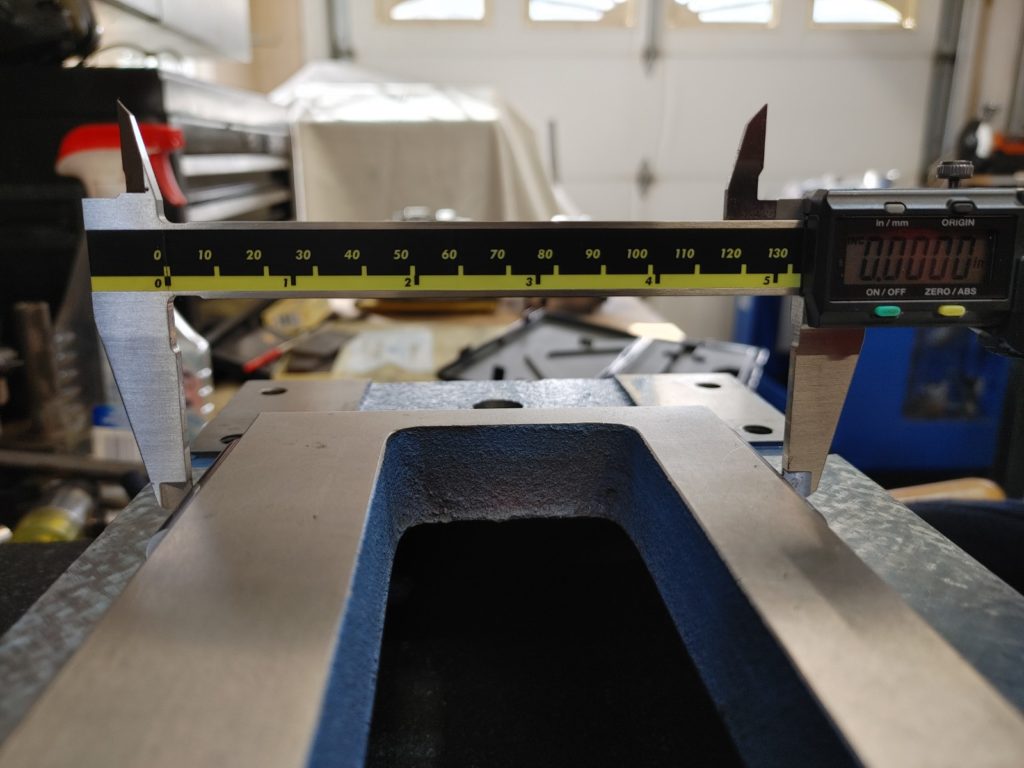
Next, we want to make sure that the dovetail ways on the base casting are flat and parallel to one another. We first get a rough sense with “very near” calipers and two precision gauge pins (barely visible below), which show that the ways are closer together by about .0015 toward the back. Since we’ll only be scraping to achieve uniform contact at this point it doesn’t matter how exact the measurement is just yet – just that the spot is detectable and the measurement is repeatable.
The dovetails are inked using the dovetail edge of my cutoff and hand scraped surface plate.
And after a few rounds, we get even inking across the ways. Checking with a more precise micrometer, the ways measure at the same distance (give or take a tenth or two) across the length of the base.
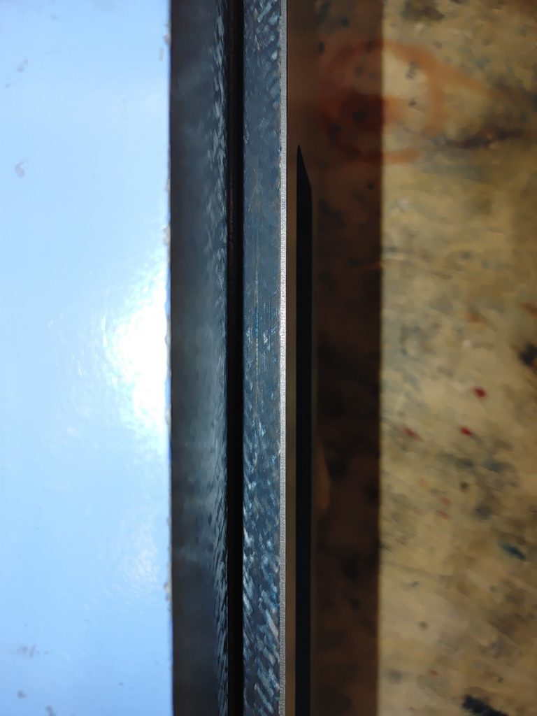
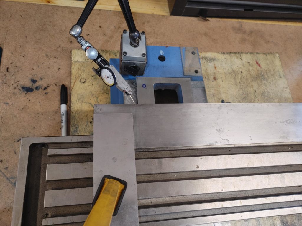
We’ll call this good enough for now. A preliminary test for X-Y axis alignment using a 20″ Brown and Sharpe precision square shows that the the X axis is out of square with the Y axis by about 5 thou over a 10 inch distance.
Some of this might be the table dovetails, which still need to be scraped, and some may be the saddle dovetails. We’ll move on to the table next and then retest to see which it is as one of our final steps.