I am very pleased with my Kearney & Trecker 2HL vertical mill. It is a marvel of mechanical engineering –robustly built and full featured. (In other words, more mill than I deserve).
As great as it is, one area where the Kearney & Trecker falls down compared to Bridgeport-style knee mills is the absence of a quill that can easily be extended from the head for drilling purposes. Instead of the familiar lever, the K&T sports a front-facing hand wheel that engages the rack and pinion assembly inside the head to lower the spindle. This setup is exceedingly rigid and works fine if you take the time to set it up (save for the occasional broken clamp collar). However, when casually knocking out a few holes, it is really easy to break bits or to drill too far because you can’t feel what is going on with the bit pressure.
To recover this casual drilling capability while letting the K&T do what it does best, I’ve decided to seriously upgrade my drill press game. I have a small CNC mill that can be used for precision drilling purposes, and can always use the K&T for larger work when I need to take my time. What I lack, though, is a more capable drill press with a large table that can stand in for the mill for everyday drilling where power, feel and ease of setup are the operative goals.
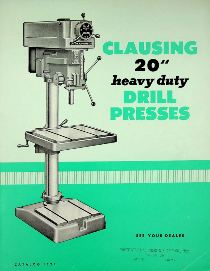
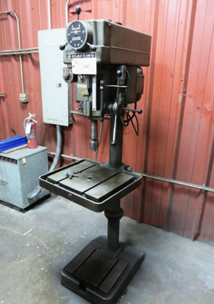
To make this happen, I began to look around for a reasonably priced Powermatic 1200 or a Clausing 20-inch “heavy duty” drill press with a production sized table. When I saw a Clausing 20 for sale at a relatively close industrial auction in South Carolina, I pretty much knew it would be coming home with me. Over the next 2-3 posts, we will document the process of getting the press up and running.
So what’s so special about a Clausing 20″ (or a Powermatic 1200) anyway?
In a word? There is more of it. The Clausing weighs in at 640 pounds and is exceedingly rigid. Compared to my current Rockwell 15″, the table is almost twice as large at 22″ x 19.5″. The Clausing’s three-phase motor is a dual-speed model, running at 1-1/2 hp in “high” and .75 hp in “low” (this compares to a 1/4 horse motor in my Rockwell). Like the Powermatics and others of similar design, the Clausing also sports a variable speed drive mechanism which allows mechanical adjustment from 150 to 2,000 RPM (more on this below, unfortunately). Running off of a VFD, this will allow tremendous adjustment in speed.
The Clausing’s column is a beefy 4″ in diameter, with a clever rack and pinion adjustment mechanism that effectively allows the table to be raised and lowered over the entirety of the column. The spindle has a healthy 6.5″ of travel and the spindle taper is a #3 Morse. This happens to be the same taper as the tail stock of my LeBlond Regal lathe. I already have a bit of tooling and some large MT3 drill bits for the LeBlond, so this interoperability will be welcome.
With the larger table, more powerful motor, more rigid frame, and more refined speed control, I’ll be able to tackle larger pieces not possible on the old press, and in the process relieve the K&T of the sort of everyday “casual” drilling duty it really isn’t cut out for.
Safely Transporting a 20″ Drill Press
As expected, I ended up winning the Clausing. After settling up (the price was reasonable), I rented a small trailer for the 90-minute drive to collect it. Doing my homework, I saw a number of folks in various forums wringing their hands over how to move these heavier industrial presses.
And they are right to be concerned: as mentioned above, the Clausing weighs in at a svelte 640 pounds. That is itself manageable with a bit of help, but the real challenge is that a good part of that weight is concentrated at the top of the machine, rendering it exceedingly top heavy. In researching the safest way to move industrial sized drill presses, I ran across a lot of various (if not contradictory) recommendations ranging from furniture dollies to engine hoists to move the machines, and transport strategies that included leaving them upright as well as laying them down flat in a trailer to rest on old tires.
For anybody in a similar situation I’ll not say that the method I ultimately went with is the best, only that it worked for me and seemed like the safest route. Loading was easy insofar as the auction rigger got a forklift blade under the head and lifted it right up and into the trailer. Given the funky weight distribution of the press, I personally would not have attempted loading it on my own without a forklift.
In terms of securing the machine for transport, reading the Clausing 20″ manual I saw that the head can actually be lowered by supporting it on the table with a 4×4, loosening the two clamp bolts on the head (537-063 on the diagram below) as well as the clamp collar below the head, and then using the table crank to gently lower it down. The column in my case was coated with decades of grease and coolant, and it ultimately took a lot of “persuading” to get the head down to a safe level, but in the end it worked.
That done, I hooked four ratchet straps to the top of the drill press column (think guy lines hooked to the top of a radio tower, or a circus tent) and secured them at 4 corners of the trailer. With the head lowered and the straps under tension, this was exceedingly stable and I had no issue getting the press home. (Sorry, I forgot to take a photo). At the shop, I used a bog standard engine hoist with a strap around the (now lowered) head to get it off the trailer. Easy.
Disassembly
Drill presses are relatively simple machines to work on, though the Clausing and Powermatic style presses complicate matters with their variable speed drive mechanisms (foreshadowing, this). As such, I knew that I’d be completely disassembling and cleaning the press, which raised the next issue – how to take the heavy castings of a 640 pound unwieldy machine apart without breaking anything.
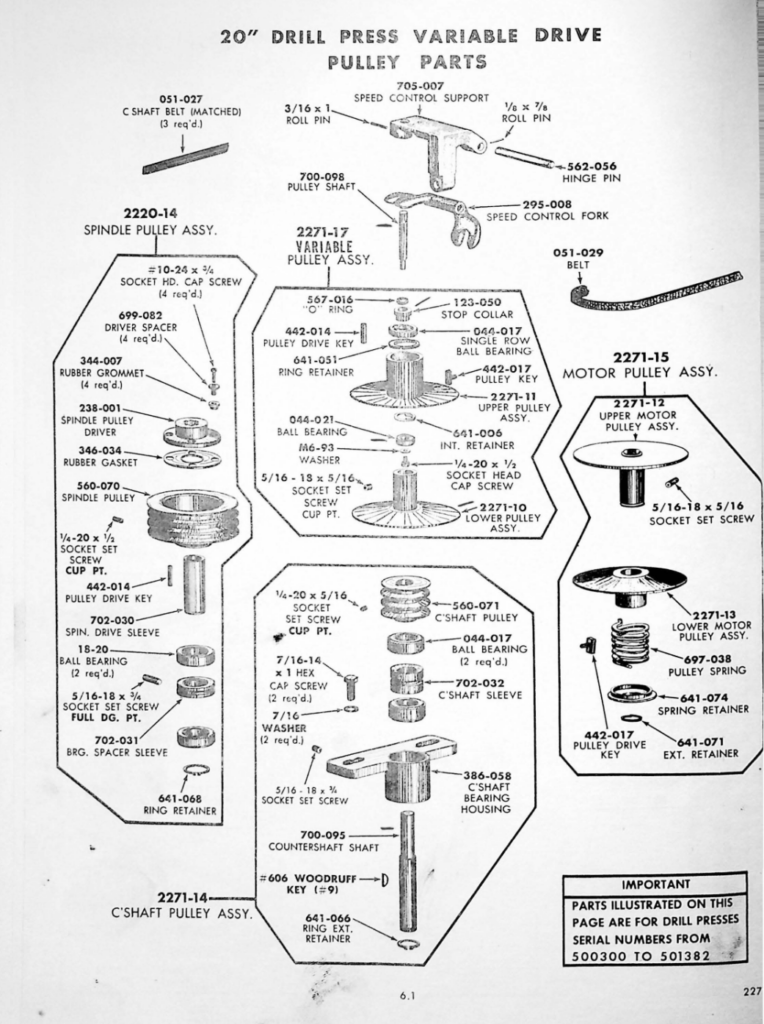
Following forum advice, I ultimately decided to remove the motor, spindle, and variable speed pulleys, then lay the press down to rest on the two points of the table and base. Disassembling the head was straightforward: the variable speed drive intermediate shaft (see second picture below) is secured by two bolts that ride in slots, which allows you to tension the drive belts. With the motor off, I was able to angle the pulleys and remove the belts, then lift the variable speed drive countershaft assembly off the head as a unit. Relaxing the tension on the quill return spring (697-018 in the picture immediately below), the spindle can just be extended all of the way out of the head and removed.
With the major components off/out of the head, I used my engine hoist to lower the press to rest on the table and the base. With the press column now horizontal, it was relatively easy to “walk” the head off the column, followed by the table, then the base. It was at this point that I noticed that the lever used to lock the table in position was not engaging, signaling work to do down the road. All in all, disassembly took about 3 hours.
Inspection: The Good, the Bad, and the Ugly
With the head off and disassembled on the bench, I was able to see that most of the bearings were in good shape. I measured .003″ in spindle runout (measured at the taper nose). Not bad for a drill press, but I went ahead and ordered new upper and lower spindle bearings to see if we can do better (044-017 and 18-17 in the first diagram above, about $20-25$ each, NOS). There are two additional bearings in the spindle pulley assembly (18-20 in the diagram immediately above). These seemed fine.
Where things started to look less rosy was upon disassembly of the variable speed drive assembly. To get the assembly apart there are a couple of set screws to remove: one securing the countershaft sleeve (702-032) in the countershaft bearing housing (386-058), and the other securing the countershaft pulley (560-071) to the countershaft. With these out, the countershaft bearing housing could be driven off toward the bottom.
At the top of my countershaft there was a grease cap and below it a nut threaded onto the end of the countershaft. That removed, I was able to pull the Speed Control Support, fork, and upper pulley off the top of the shaft. I found I had to press the lower pulley assembly (2271-10) off the shaft toward the top (note, the shaft is stepped – you’ll break it if you try to press it off the bottom).
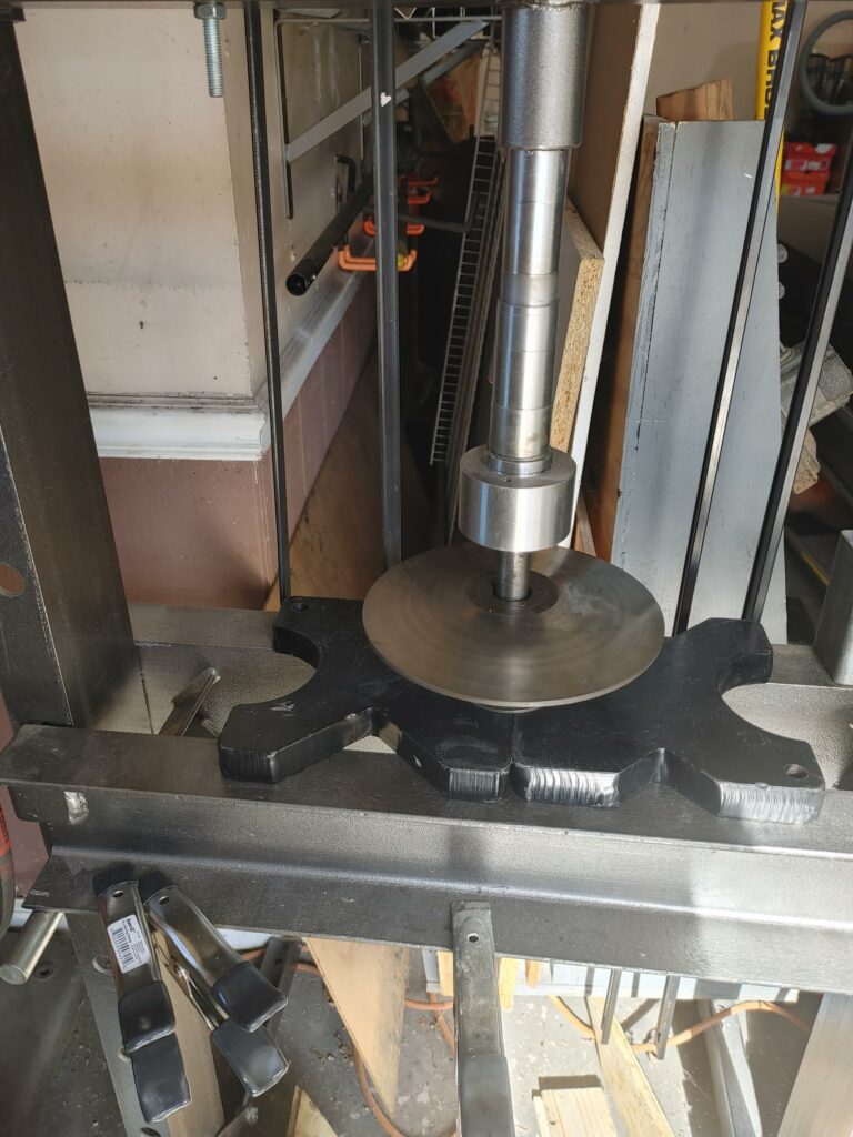
With the countershaft free, it quickly became clear that we have issues. While the upper bearings were fine, one of the two lower bearings (044-017) had seized and spun, wearing a groove in the shaft.
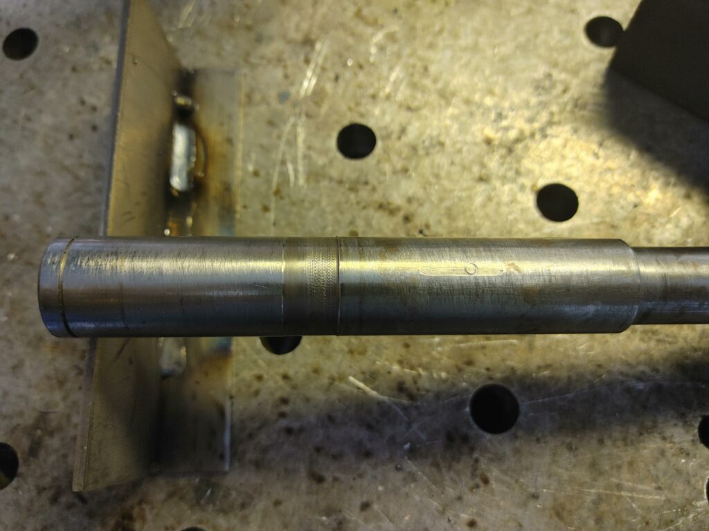
Bad enough, but wait, it gets better. The way the variable speed drive assembly works is that the upper pulley rides up and down the shaft, with downward pressure from the fork keeping it in place and in tension with the variable speed belt connected to the motor. Given the shape of the pulleys, this movement increases and decreases the effective diameter of the combined upper and lower pulleys, allowing the countershaft to spin slower and faster, respectively.
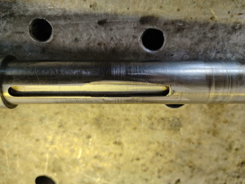
To facilitate this functionality, a pulley key (442-017) is inserted through the upper pulley sleeve. This key is kept in moderate tension by a spring and rides in a keyway on the countershaft, fitting tight enough to keep the pulley from spinning on the shaft, but loose enough to allow it to move up and down the shaft as the fork applies and releases pressure. In my case, the key had wallowed out the keyway, allowing for excessive play (and, I believe, at one point jamming the upper pulley in place and locking the press into a single speed).
So here is the rebuild strategy : First, we’ll replace the spindle bearings and the two lower variable speed drive bearings. The drill press will also get new belts and generally get cleaned up and painted. Next, our major repair work will involve fixing the variable speed drive countershaft where the lower bearing has spun and where the keyway has been wallowed out. We’ll also address that pesky table lock that doesn’t seem to want to lock. Finally, we’ll get the 3-phase 1-1/2 hp motor running on a VFD and — if everything goes to plan — return this workhorse to (relatively leisurely) service.