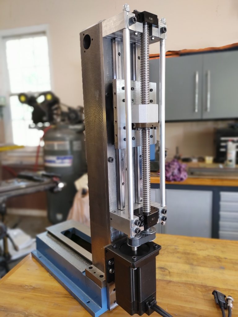
In the last installment of our Sieg Chinese mini mill CNC conversion we installed linear rails and constructed a sliding saddle mechanism tied to the head assembly to increase rigidity. Now we will complete the Z-axis assembly by installing a heavier duty 2005 ball screw and Nema 34 Stepper Motor.
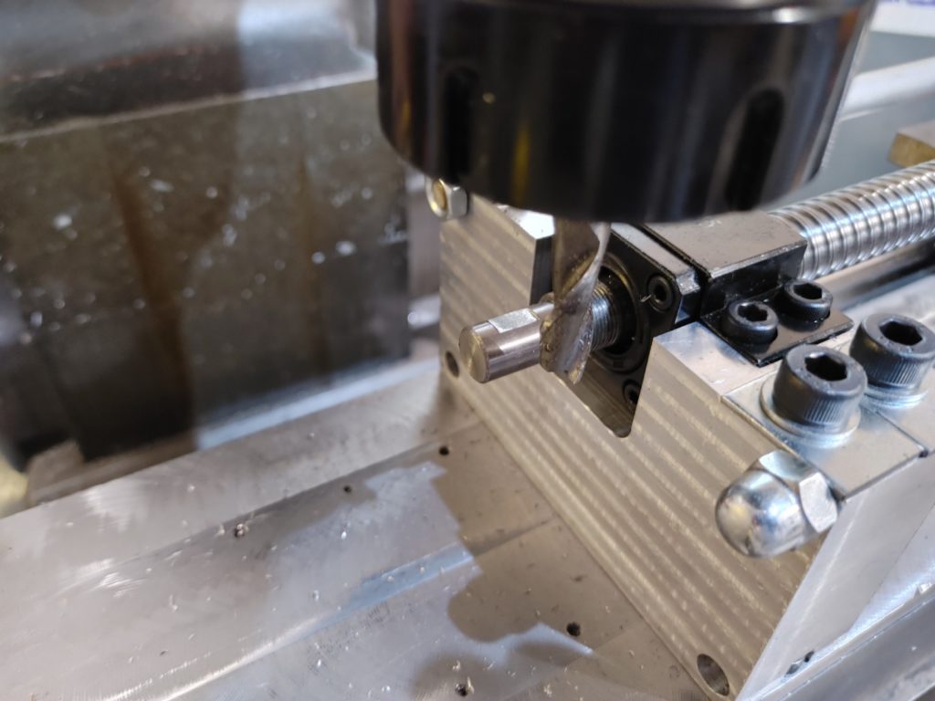
I intentionally decided to mount the ball screw nut on the top side of the linear rail saddle to keep the attachment point as close to the head as possible. To do this, we need to raise the bearing housings through use of two riser blocks.
I designed these in Fusion 360 so that the stock bearing blocks would bolt directly to the risers. This was made more complicated than it needed to be by the spacing of the bolts holding the back plate to the column and by the bolts mounting the rails to the plate (dictated by the wide spots in the castings and pre-drilled rail mounting holes). While designing the risers, I added through holes so that the blocks could be tied together with a threaded rod and spacer assembly.
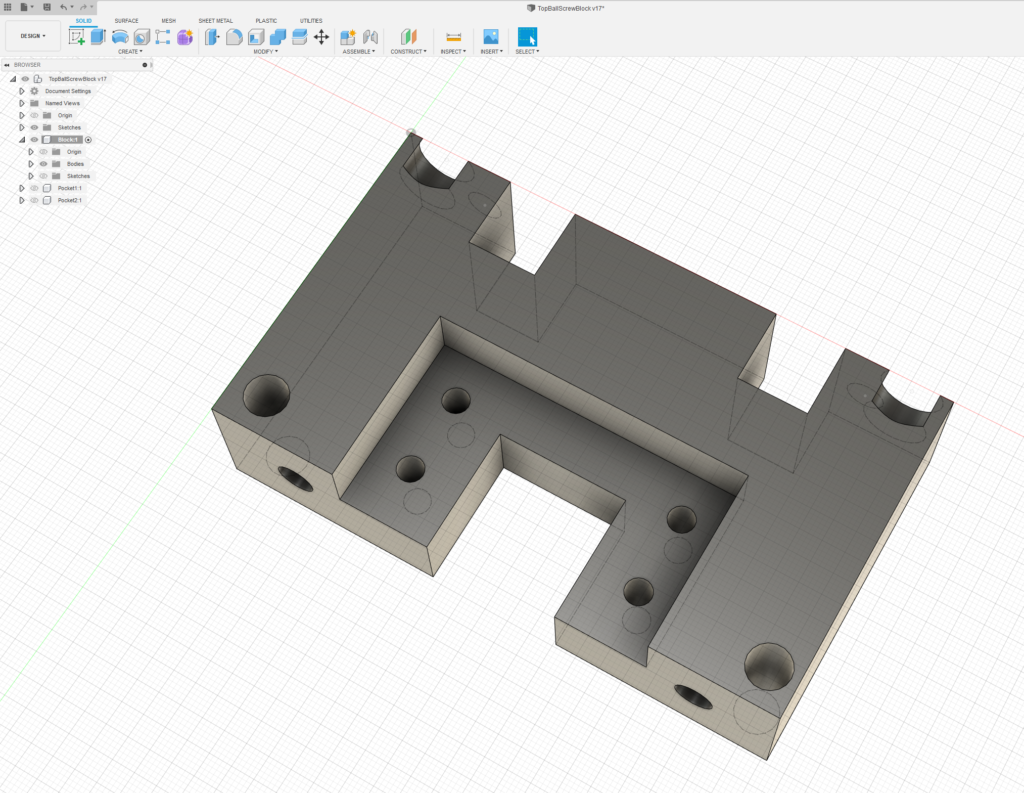
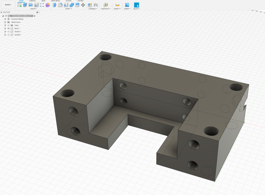
After drawing the design in Fusion 360, I printed the prototype out using a 3d printer to verify that I had measured the dimensions correctly. Satisfied, I used the Bench mill 6000 that we got running earlier in the project cut the risers from 1.5″ aluminum bar stock.
I had to eventually relieve the corners on the riser pockets using a conventional mill, and to enlarge a couple of mounting holes, but everything else fit up properly.
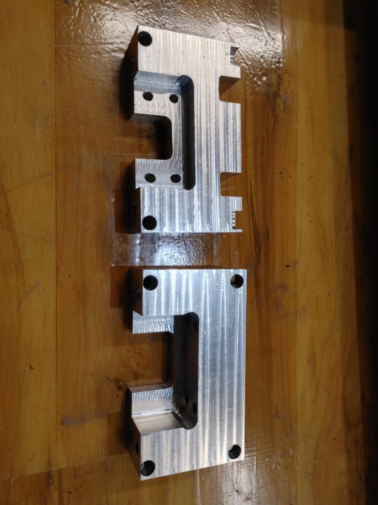
I then used M6 and M8 bolts to bolt the risers to the steel back plate. Using 3/8 threaded rod and 1/2 aluminum tube as a spacer, I then tied the top and bottom blocks together. (In the pic below, you can see the bottom pulley fitted for spacing purposes).
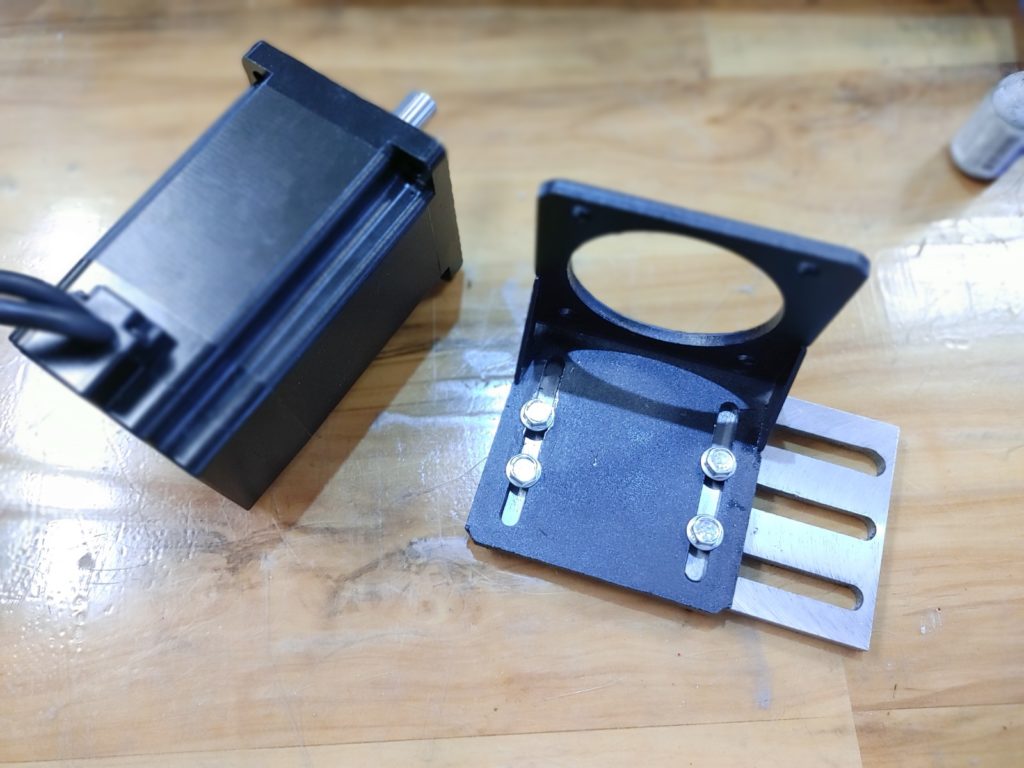
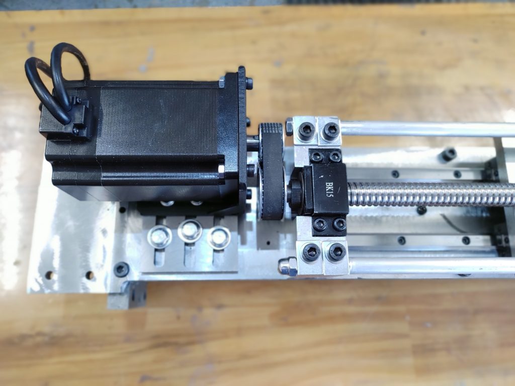
The next step was to create a mounting plate for the Nema 34, 9Nm stepper motor. This size motor is probably overkill, but I’ve added a lot of weight to the head, and even with a strut offsetting the weight, it won’t hurt to have the power.
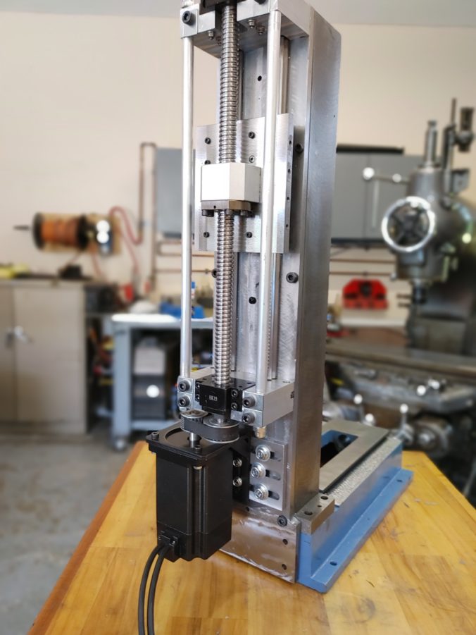
I could have fabricated a full mounting plate, but for $14, I was able to get a Nema 34 mounting bracket, which I simply bolted to a custom plate from 3/8 flat bar stock with slots conventionally milled in it. The combination allows both X and Y axis adjustment for the motor.
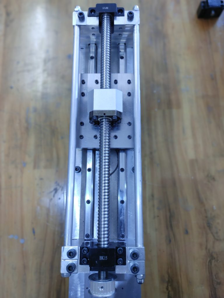
Because the original mill uses 1204 ballscrews and I’m substituting a beefier 2005 Z-axis screw, I have to use “gear reduction” to ensure that the same signals sent to the motor result in similar movement along the ballscrew.
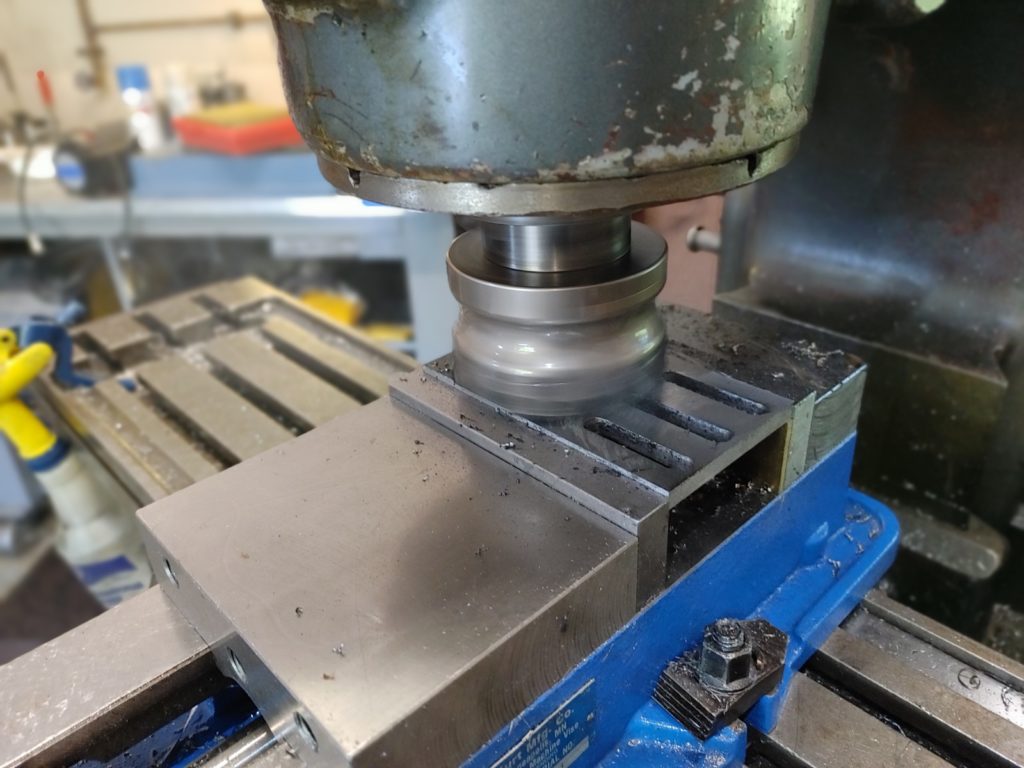
Attached to the motor is a 20 tooth, 16mm pulley and to the screw is a 25 tooth pulley. After milling flats onto the shafts to prevent slippage, I fixed the pulleys with Locktite 640 and two set screws for each pulley.
Connecting the pulleys is a 200-5m-15 belt which just barely gives enough clearance but leaves almost no room for stretching or slippage. Here is everything tightened down.
And … the final product. With the work done to strengthen the head, and once we fill the column and base with epoxy, we’ll be working with a much more stable, rigid head. Reading others’ observations and based on my own look at the Z-axis dovetails and somewhat questionable gib geometry, I definitely see this as the primary weakness of the Sieg 2.7 design. Knock on wood, I think we’ve engineered our way around it.
Next up: mounting the Y-axis ball screw and scraping the X-axis.