
In earlier posts on our CNC mini mill project we reinforced the mill head and column. Now that we have the rigidity we need, we’ll focus on an upgraded spindle. We are already off to a good start: as a cost saving measure, when I first purchased the Sieg 2.7 castings from Little Machine Shop I purchased a R8 spindle cartridge, which includes items 2, 3 and 30-37 in the parts diagram above. I knew this might only be a partial solution, however, since the description indicated that the cartridge was rated for only up to 2,000 RPM.
For CNC work, I want to be able to achieve at least 5,000 RPM. Initial research showed I could probably get there with this cartridge: replacement bearings for this spindle (used on the Sieg SX2.7, as well as the X3 and SX3) can be had that are capable of 6,300 RPM and above on grease. I also saw a number of comments from owners of X3 and SX3 machines who were getting 4,000-4,500 RPM out of this spindle, stock.
My initial reaction after reading this was to leave the cartridge well enough alone and to see if it actually heated up with high RPM use. However I made the mistake of testing it for runout and saw that it exceeded 0005″. Not terrible, but not great either given all of the work we are putting in the mill. Irredeemable anal retentiveness meant that a spindle upgrade was going to be in the cards …
Doing some additional internet sleuthing, I encountered a number of comments attributing overheating of this spindle at >2,000 RPM to inferior grease used at the factory. Still others noted that the original spindle design employs a regular ball bearing and thrust bearing combination in the upper spindle (36 and 34 above). In a couple of instances, owners have reported replacing these with a tapered roller bearing to good effect.
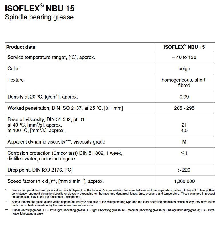
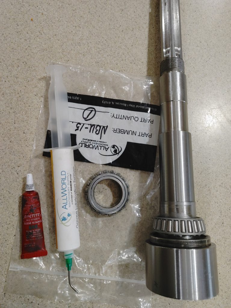
All of this made sense to me, so my initial shopping list included a FAG 32006-X tapered roller bearing to replace the upper ball bearing and allow omission of the stock thrust bearing. The FAG bearing is rated for 13,300 RPM and has a static load capacity of 46,500N. I also ordered a 30G syringe of Kluber Isoflex NBU-15, recommended by multiple folks as a good, though pricey, spindle bearing grease. In the process I learned all about grease “speed factor” and learned that the Kluber grease has a factor 1,000,000, compared to 400,000-500,000 for most lithium/mineral oil based greases.
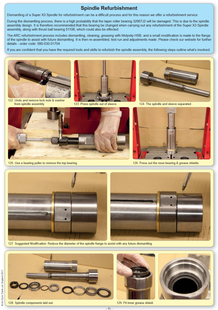
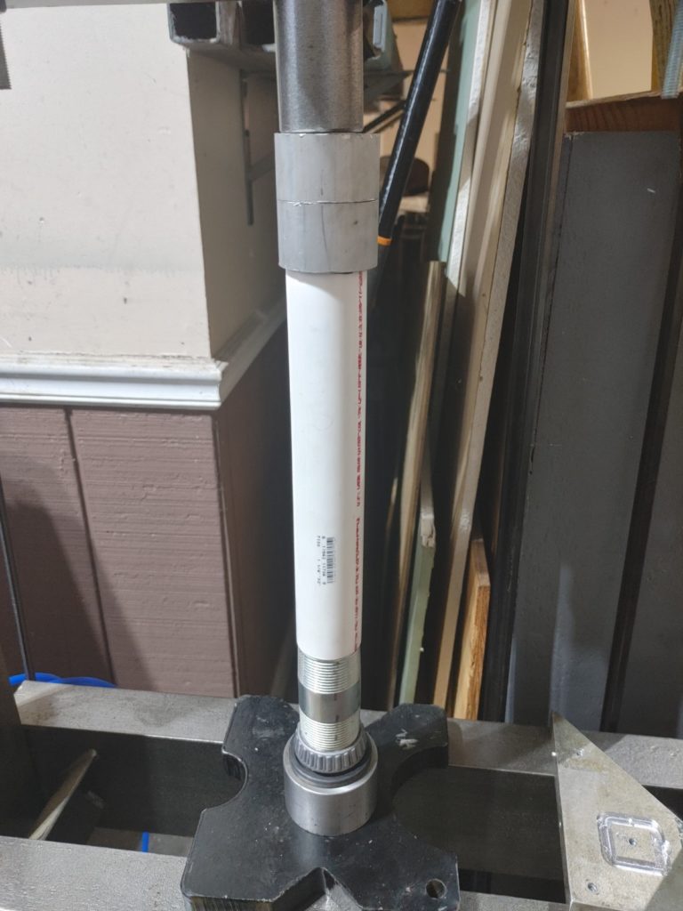
Disassembly of the cartridge was trivial following the excellent instructions for X3 mill disassembly at Arceurotrade.com. The only improvement I added to these was the wedging the spindle sleeve in a grinding vise when pressing out the spindle shaft. This avoided the need for some of the special tools illustrated there.
Once separated, I put the spindle shaft on angle blocks and confirmed that it actually had nearly a thou runout. To my horror, I noticed that the shaft journals were visibly offset on one side where someone at the factory had attempted to correct an out of alignment taper.
After a doomed attempt to correct this on the lathe, I ordered a new spindle shaft, together with a second lower tapered roller bearing (NSK HR 32907J), rated at 6,300 RPM. I ordered the replacement bearing with the, as it turns out correct, assumption that it would be difficult to remove the old lower bearing from the original spindle shaft without damaging it.
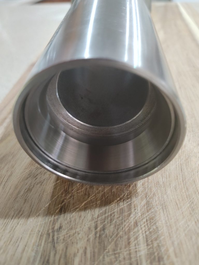
Using a conveniently sized PVC pipe, I was able to press the new upper taper roller bearing race in the original spindle sleeve without much difficulty. I was a bit concerned as the inside wall of the sleeve is stepped to allow the thrust bearing in the original design to sit below the regular ball bearing that I was replacing (see photograph below). This meant that the new race, without the thrust bearing, overhangs the lip by a millimeter or two.
If this application was going to result in significant downward axial force I would have machined a spacer, but since I’ll be implementing a power drawbar arrangement which squeezes the drawbar against a “top hat” screwed to the spindle shaft end (more on this to come), I was comfortable omitting it.
My next step was to thread the end of the new spindle shaft at a 12 thread per inch pitch. As mentioned, this will allow me to thread a top hat to the end of the spindle shaft against which a set of Belleville washers will push to keep tension on the drawbar (if this is hard to visualize, never fear – it will become clear soon enough).
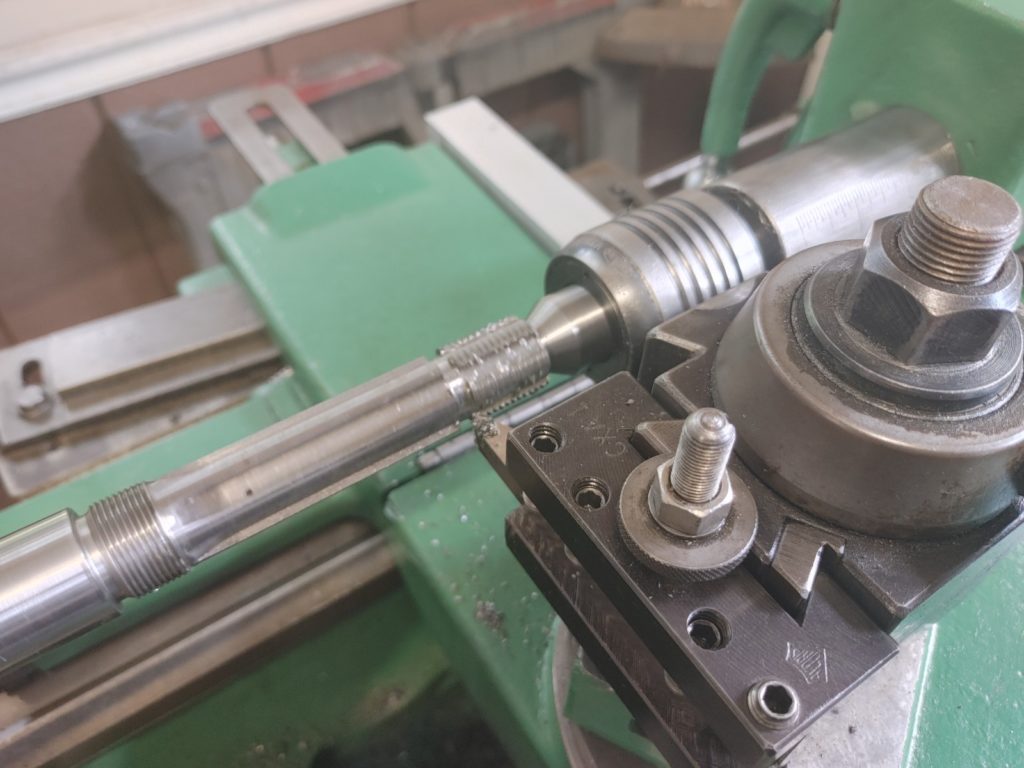
With this done, I set the new shaft on angle blocks to test for runout at the taper nose. I was relieved to see slightly less than .0005″. With plenty of “meat” still on the shaft journals, I identified the low spot and set the spindle shaft up in the lathe with the opposite side of the journal reading high by the same amount. I then took a light “dusting” cut at .0001-.0002″. This only “shaved” the high spot (you can see the untouched bluing in the photograph below). Returning to the angle blocks, runout was reduced to a few tenths with the diameter of the journal still thick enough for an interference fit with the lower bearing inner race.

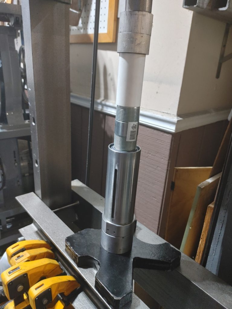
I then pressed the lower tapered roller bearing onto the shaft, adding a dab of Loctite 640 to ensure that the inner race would not spin following my efforts to true up the journal. I found that a bog standard 1-1/4 threaded pipe connector from Home Depot aligned perfectly with the inner bearing race and allowed me to gently press it home with the assistance of a bit of PVC. Note: there is a grease seal that goes on first – forget that, and you’ll have to remove the lower bearing and start over!
Next, I packed both upper and lower tapered roller bearings with the Kluber NBU-15 at about 30% of volume.
I then gently pressed the bearing sleeve onto the spindle shaft (seating the grease shield – black in the photograph above). Following this, I pressed the upper tapered bearing onto the spindle shaft until no end play was detected, while the shaft could still turn freely. I then secured the two crown nuts.
With the spindle compete, I tested runout at the spindle nose, which exceeded my wildest expectations. At most, it is under .0002″, and some of that may be down to imperfections in the taper. Far better than any import Chinese spindle assembly has a right to be and with the upgraded bearings and appropriate grease, we should be able to hit the 5,000 RPM mark we need. Color me happy with this phase of the build.
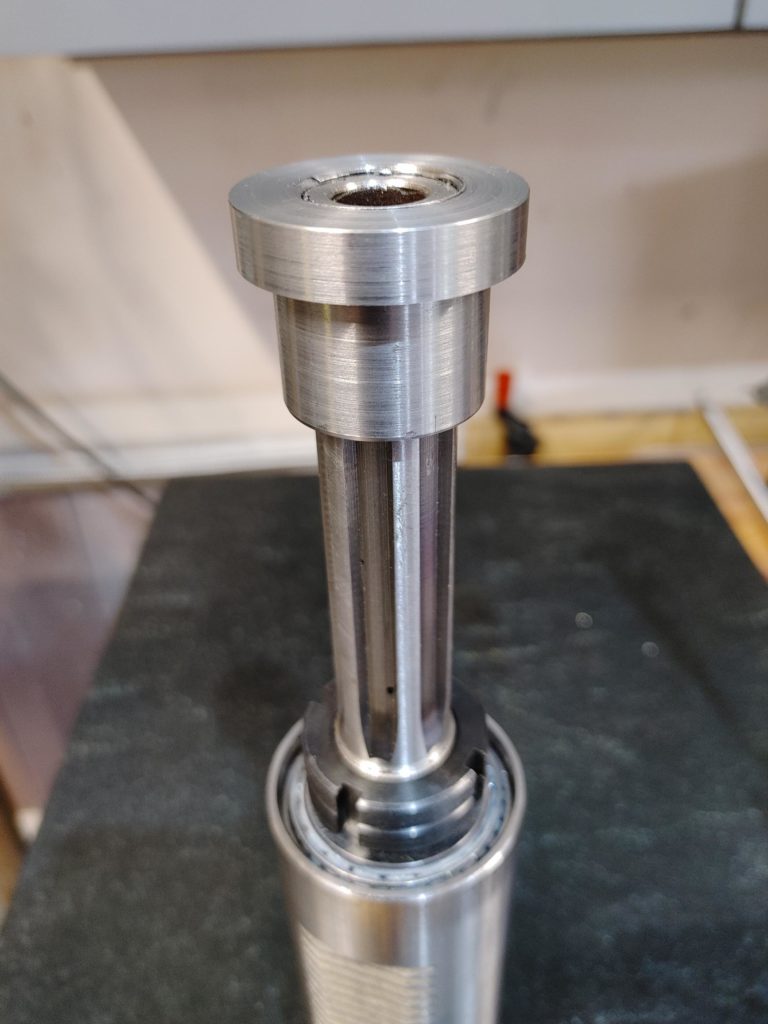
As a final item, we’ll turn the tophat to thread to the end of the spindle. A stack of Belleville washers will sit on top and will keep tension on the drawbar. An air cylinder will compress them when it is time to change the tool.
Here it is threaded on the end of the spindle shaft.
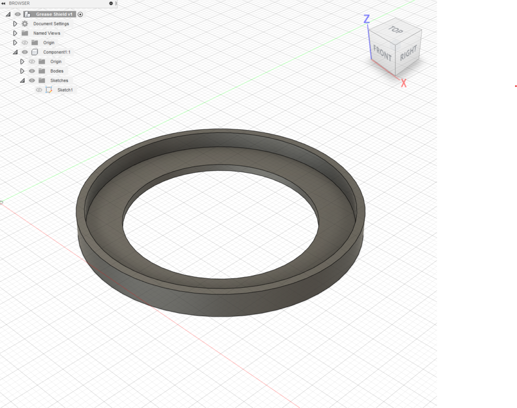
If you look at the base of the shaft, you can see the exposed bearing rollers. That is no good– if metal particles or grit were to fall into the bearing, things will head South quickly. So as a final touch we’ll whip up a grease shield that fits into the lip of the spindle sleeve. We’ll print it in TPU so it has some flex.
Here it is installed with the tophat:
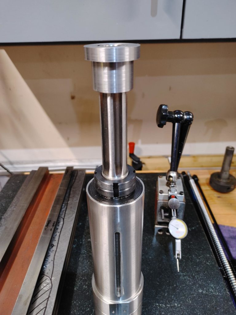
As a final step we’ll run the spindle in on the lathe and adjust preload one last time. Ten minutes at 1200 RPM has it barely getting warm.
We’ll call it done. Next up: installing a 1.5kw servo motor in the head for increased power.