Inspired by this blog entry, one of our first modifications to the Sieg x2.7 castings will be a reinforced column to improve rigidity. Our strategy will be a bit different from the one used there, though. Because we will be installing the z-axis lead screw on the outside of the column as part of our approach to stiffening the head (more on that later) we can afford to enclose the entire column, from top to bottom, while leaving a 3-inch tab at the bottom to attach to the base.
To do this, I opted for half-inch thick, 6-inch hot rolled bar stock cut to the the length of the column plus the base so that it can attach to both and tie them together. Once the plate is installed, the plan is to fill the column with epoxy granite via the gap in the front side through which the head attaches to the lead screw that is located inside the column in the original design.
Our first step is to trim the 6″ bar stock to close to the 130mm width of the column. Because we will be using side brackets flush to the column sides to attach the head to the lead screw (and a couple of linear rails mounted to the back — again, more to come), it is important to get the width exactly right.
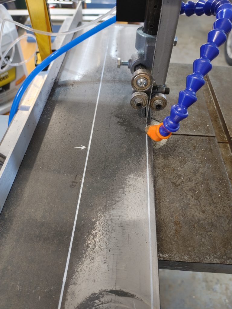
We start on the band saw:
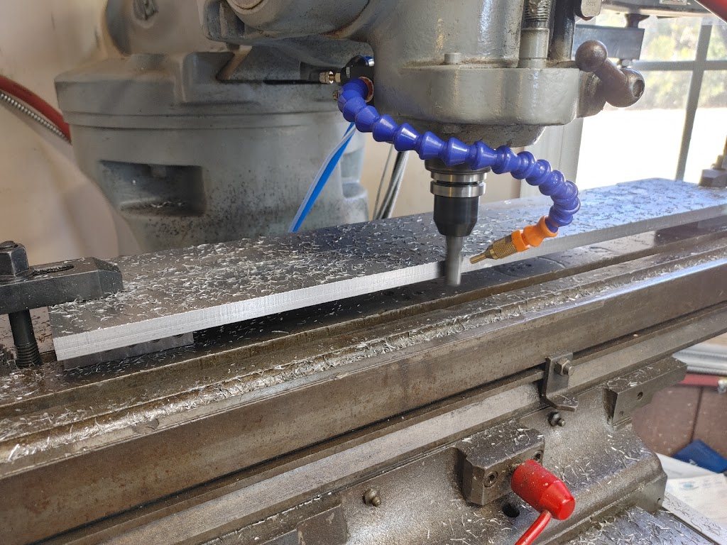
And finish to size on the mill:
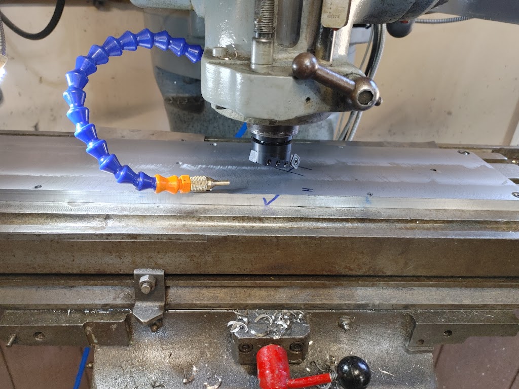
Because our design will see linear rails mounted to the back of the column, we need to get the plate relatively flat. We first attack the mill scale with a fly cutter.
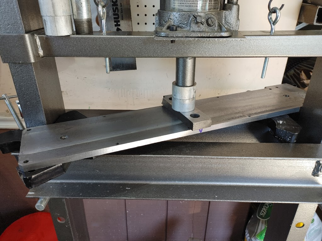
Of course, once we cut into the plate, it is going to warp. Instead of endless fly cutting, we can bend it reasonably straight using a shop press, then give it a final pass, front and back, using the fly cutter. At this point, it measures flat to within 15 thou across the 28″ length.
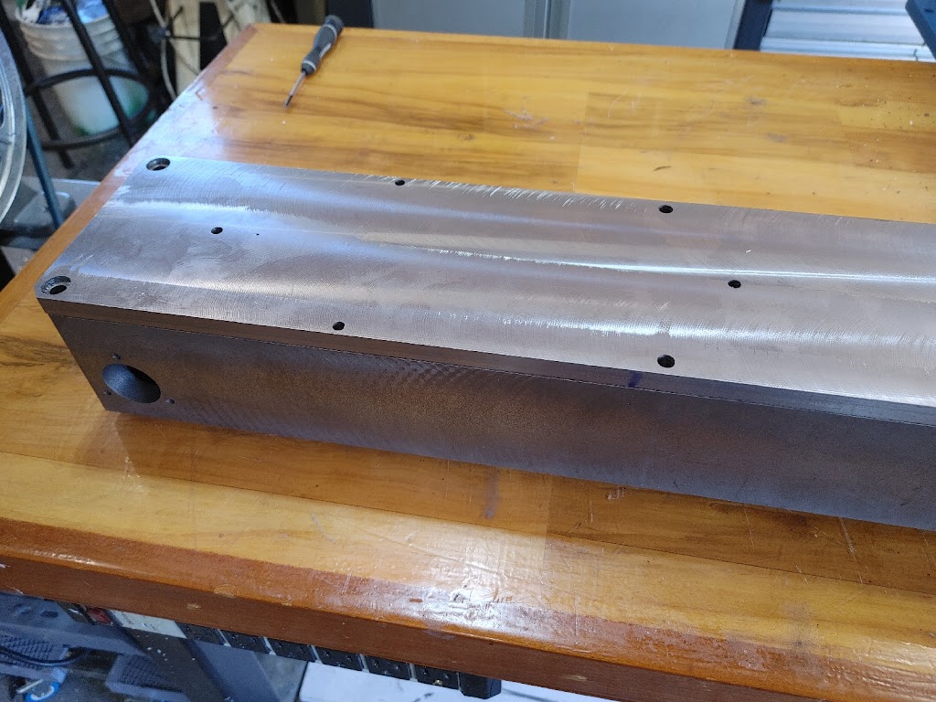
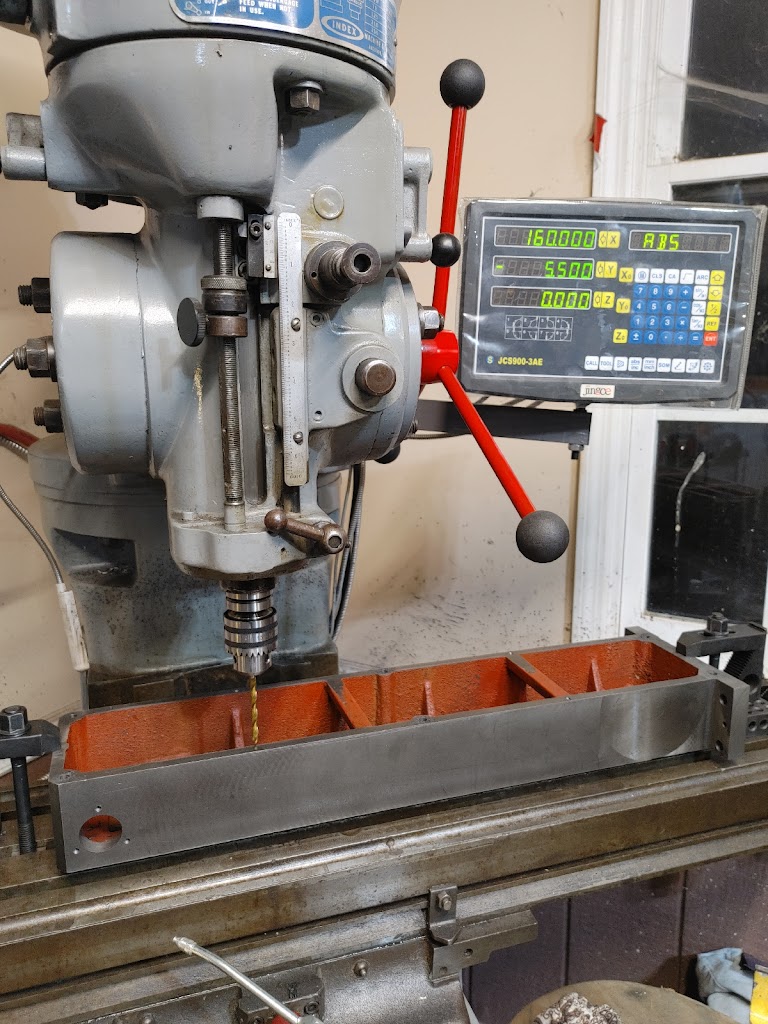
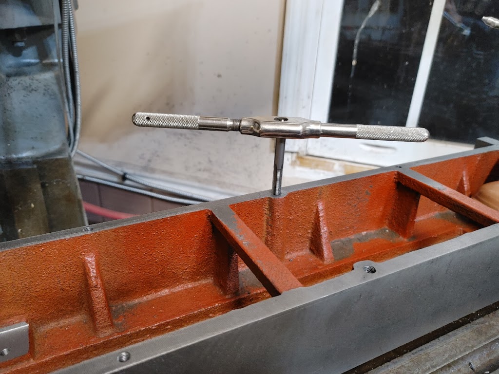
Next we drill and tap the column, using a DRO to record the position of the holes. I’m using M8 and M6 cap screws here (depending on how wide the casting is at the various drill points).
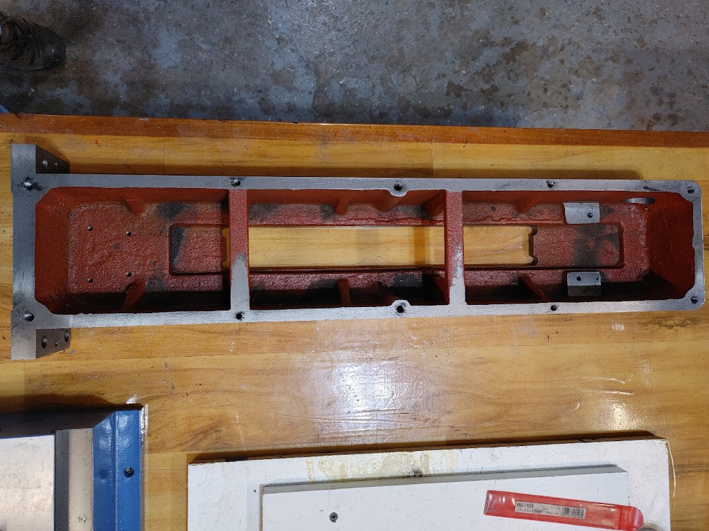
And here are the final hole locations. You can see where the casting has six points that allowed me to tap for larger M8 cap screws. The M6 cap screws are used at four points where the casting is thinner.
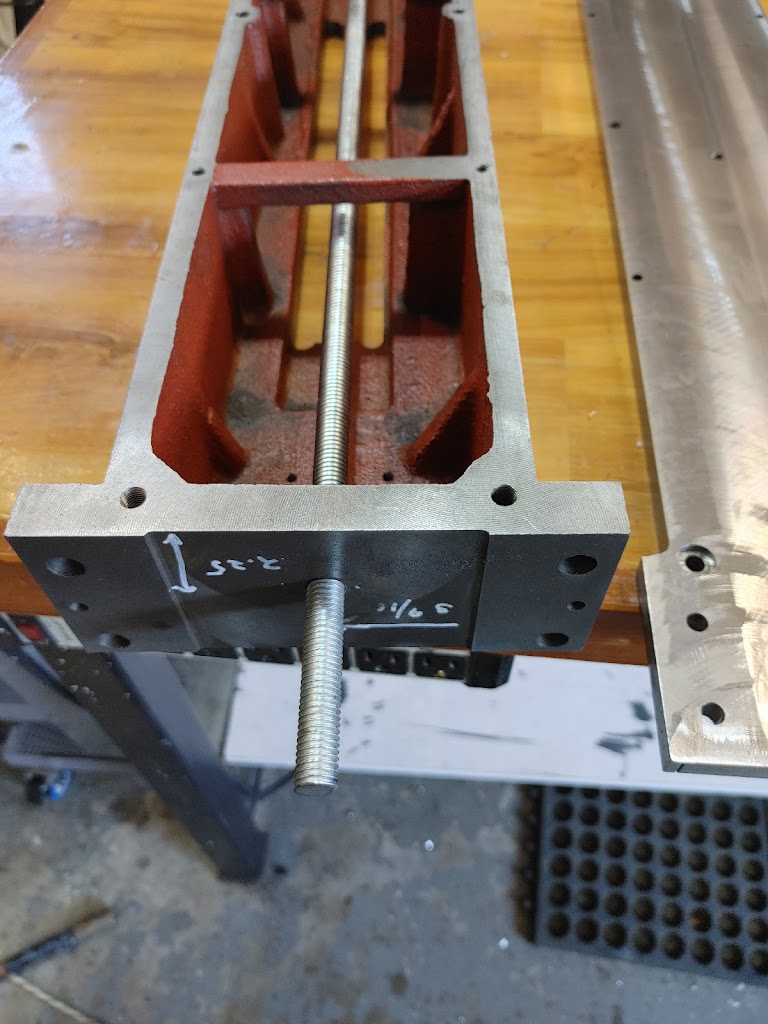
For good measure, we can drill a 1/2″ hole and insert a length of threaded rod, held taught by a nut on the bottom of the column casting (not visible here). This isn’t to provide rigidity, per se, but to give the eventual epoxy granite something more to bite into, while providing a fifth anchor point into the base. The base will get its own epoxy granite pour once the column and head are trammed, tying everything together.
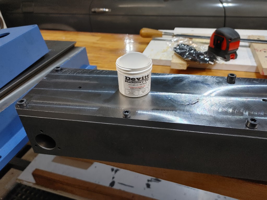
And finally, we use some machine epoxy to level the plate on the base. Here I’m using a 50 gram kit of DWH putty from the nice folks at Devitt Machinery. By selectively tightening the bolts and letting the epoxy cure before tightening the rest, I was able to get the back flat to within 5 thou over the 28″ length.
I’m happy with the result. When it is time to install them, I will further level the linear rails to the back plate with machine epoxy which should keep everything straight and prevent binding.
Next, we’ll move on to scraping the ways of the mill castings.
