Having reinforced the head and upgraded the spindle motor of the new Sieg 2.7 guts going into our Benchmill 6000 CNC training mill, we’ll now complete the head assembly with an air cylinder-driven power drawbar. This will support the eventual automatic tool changer feature we are planning and, in the meantime, simplify life in the tight Benchmill enclosure.
The power drawbar design we’ll be using sounds complicated but is actually simple in operation: tool changes are made by activating an air cylinder that will press the mill’s drawbar down against a series of Belleville spring washers. When uncompressed, the washers put tension on the drawbar to pull a collet in the spindle nose tight against the inserted tool. When the washers are compressed, tension on the collet is relaxed and the tool can be removed. Here, we’ll be using the Tormach TTS system for the collet and tool holders but the principle would work with any spring-type collet.
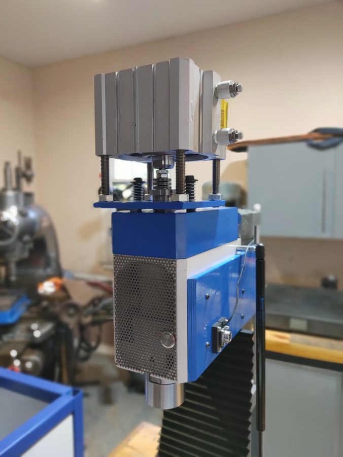
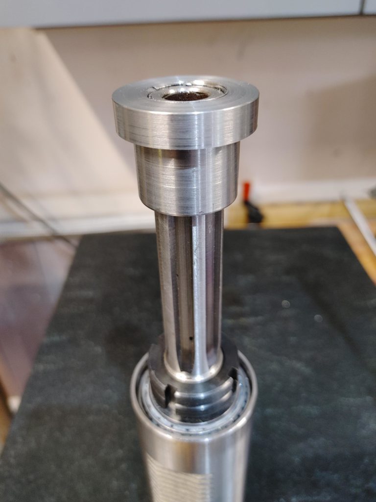
The Belleville spring washers we’ll be using will be compressed against a “top hat” threaded onto the end of the spindle shaft. The top hat keeps the air cylinder piston pressure on a fixed object (the top hat) rather than the spindle bearings. A floating base plate arrangement completes the assembly, allowing it to ride on two shoulder bolts threaded into the top of the belt cover. This keeps the spindle shaft from rubbing on any part of the assembly when the spindle is moving. None of this is particularly ground breaking: there are several good examples of this approach out there, including this one and this one.
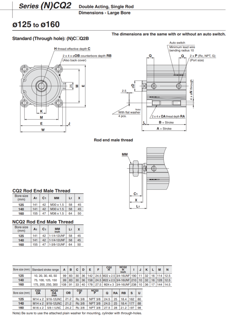
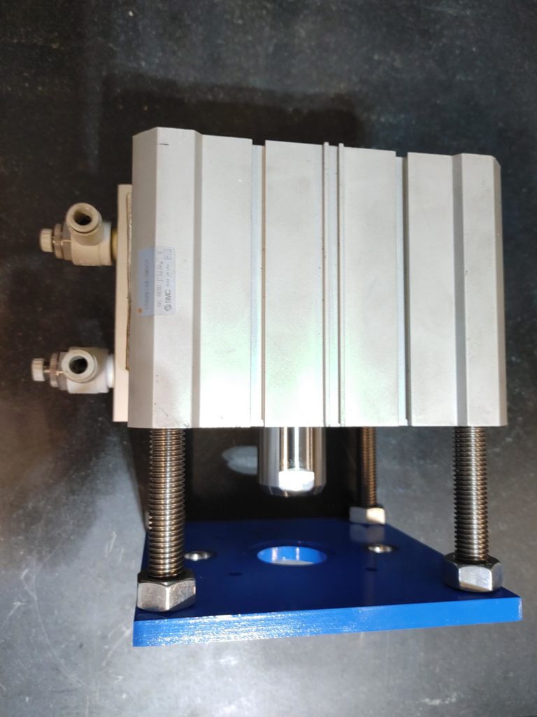
The air cylinder we’ll be using is a SMC 140mm single stage, dual action cylinder. It is bulky, but fits the profile of the machine, particularly since we’ve tucked the spindle motor into the head. I would have liked to have gone with a multi-stage cylinder to keep things even more compact, but those are costly and at $45 on Ebay, it was hard to argue with the price of the single stage option. A 140mm bore cylinder should make North of 2,700 pounds of force at just under 120psi, which seems consistent with some of the recommendations I’ve seen on pressures needed to prevent collet slip.
This is an “easy” power drawbar implementation insofar as it only requires three machining operations. In our earlier post about upgrading the Sieg spindle, we threaded the end of the spindle shaft to accept a “top hat” turned from steel against which the Belleville spring washers will be compressed to keep pressure off the spindle bearings.
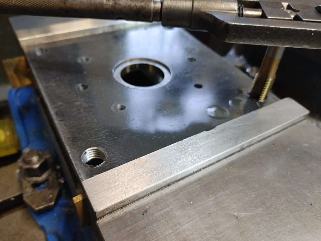
The only other machined part is the floating base plate which will be mounted to the air cylinder. Aside from the four mounting holes and two alignment holes for the shoulder bolts, it has a hole through which the spindle shaft can pass, but which catches the lip of the top hat to sandwich it against the air cylinder piston.
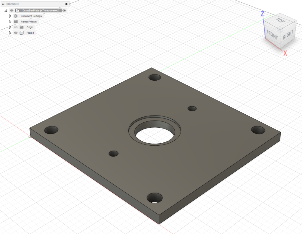
It was easy to whip up a simple design for the base plate in Fusion 360 and cut it on the Benchmill. Here I’m using 3/8″ hot rolled steel, pickled and oiled. If I had to do it over again, I would have adopted a design which utilizes a “U” shaped slot for the spindle shaft instead of a hole to make it easier to remove the assembly. As it is, I have to unscrew the top hat to remove the air cylinder, but that should be a once-in-a-year operation at most and it works just fine as designed.
The four mounting holes in the base plate were spaced to match the threaded holes in the air cylinder. Once milled, they were tapped for M14-2.0 threaded rod.
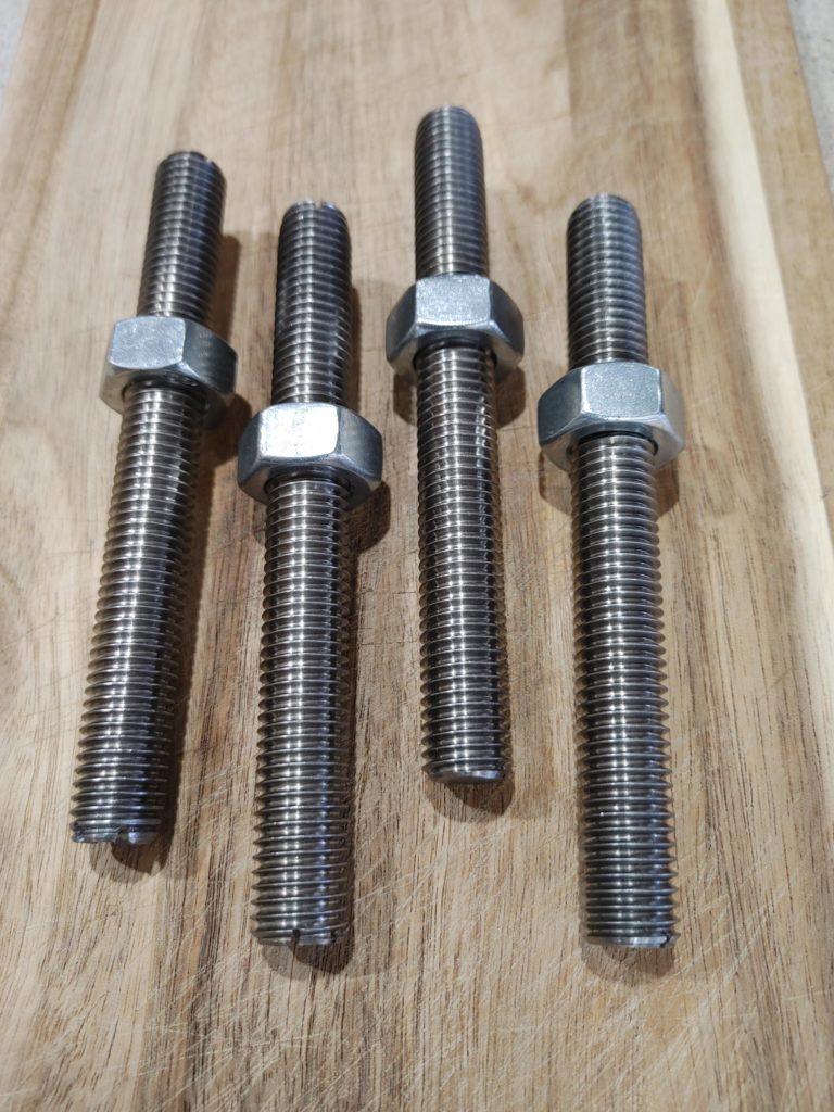
Some of the designs I’ve seen encase the threaded rod in standoffs machined for the desired height, but I opted to use stainless rod and cut slots into the ends of the rod. This allowed me to to treat them like big set screws and adjust the depth with a slotted screwdriver before tightening down a nut to secure them.
By my admittedly amateur calculations, a M14 rod completely threaded in 3/8″ of mild steel has a pull out strength exceeding 6,000 pounds (per rod). With the load spread across four rods, this should be plenty given that the air cylinder should make no more than 2,800 pounds of pressure at 120psi, and saves me from having to secure the rods with a nut on the underside of the plate (making for a lower profile design). Here is the base plate attached to the air cylinder.
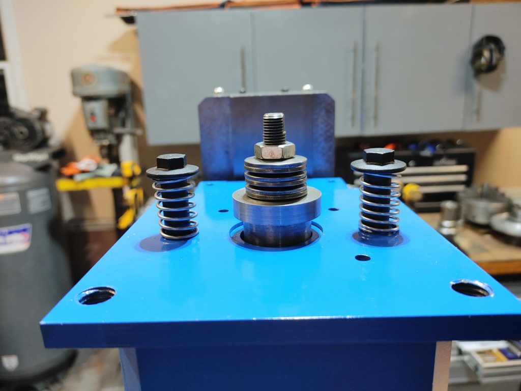
The final step was to install two shoulder bolts, threaded into the cover of the spindle drive belt, which keep the “floating” base plate aligned as the air cylinder pushes against the top of the drawbar and compresses the Belleville spring washers. I added springs to the shoulder bolts to keep the base plate pressed down against the top of the belt cover when the air cylinder is not activated to keep the assembly from rattling.
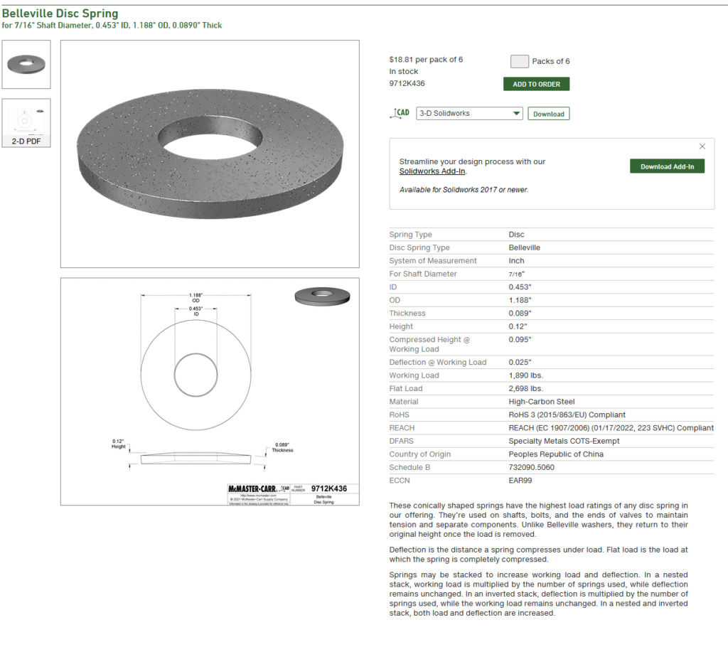
The washers I used were recommended here and with a 7/16 inside diameter are perfect for the drawbar. They begin to deflect at 1,890 pounds and are compressed flat by 2,700. At full deflection, six of them together compress by .15″ which should be enough to relax the tension against the collet and release the tool.
To finish the assembly, I milled two flats on the tip of the drawbar to allow me to get a wrench on it when tightening down the nuts which compress the spring washers. I’ll need to experiment to find the right tension that prevents slippage, but for now I’ve tightened them until the washers begin to compress, then a half turn more.
With the assembly together, it works a treat. Here I’m testing it with just the “compression” action connected. (When the retraction line is attached, the piston rod should not rest on the drawbar, or at least that is the plan).
That is all we can do on this phase until we swap out the X1 guts in the Benchmill for our shiny new, upgraded Sieg 2.7 parts.
It is at this point that the strategy of basing our CNC project around a full-featured training mill starts to pay off. The Benchmill already has a series of solenoids installed and wired to the CNC controller. Tool changes can be fully automated or initiated by pressing the momentary switch on the front of the mill head. The Benchmill also has a built in lockout mechanism to prevent the air cylinder from activating when the the spindle is moving. In theory, everything should be completely plug and play from here on out and the automatic tool changer routines already built into the Benchmill can be fully utilized. We’ll see, though. Best laid plans, etc.
Next up, we’ll construct a custom stand on which to mount our nearly complete hardware.