In Search of Lost Zeros

Adventures in amateur machine building

Kearney & Trecker 2HL – Removing Front of Knee and Disassembling Feed Distribution Gearbox

From our initial diagnosis we know that our Milwaukee 2HL Vertical mill has issues with power feed at any speed over 7 or so inches per minute. To figure out what is going on, we’ll need to pull the front of the knee (the “feed distribution box”). I won’t go into too much detail since there is an excellent video already out there, but there are a couple of key points I can reinforce here.

Most of the preparatory work to remove the box requires work on the left side of the mill, where there is a small right angle feed change worm gearbox (#9 in the parts diagram below the fold). It is held in place with three slotted screws. Before removing it, best practice is to go ahead and set the feed to the lowest setting to simplify the feed timing when the feed distribution box is reinstalled (see discussion below).

Next, we’ll need to remove the trip dogs (#52) that ride on the vertical and cross feed rods (#55 & #53). These are each held on by a cap screw and slide off to the rear. In my case, some previous jackassery had resulted in one of the cap screws being positioned such that it rubbed on the underside of the saddle. I’m not sure if this was what was throwing off the Y-axis precision as the table was cranked out, but I’ll be keeping my eye on this possibility.

Continue reading

Queen City 12″ Grinder (Model 4F)

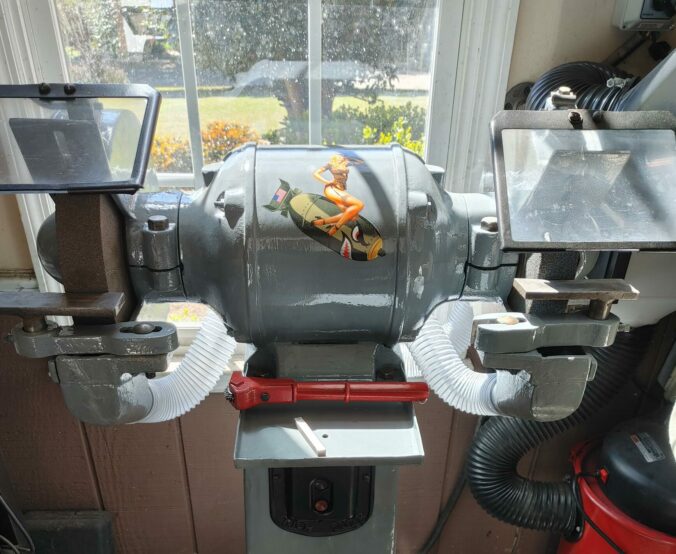
Over the last year or two, I replaced the abrasive wheels on my 8″ no-name bench grinder with a brass wire wheel and a nylon fiber deburring wheel, both of which I found I used much more on a day-to-day basis. Still, I do need to grind down welds, shape the occasional HSS lathe tool, and sharpen larger drill bits from time to time, and was getting sick of swapping out bench grinder wheels when the occasional grinding job presented itself.

The original plan was to buy a second, quality made bench grinder … maybe even a 10″ model … and devote it to actual grinding. However, the good bench grinders seem to be caught up in the post-COVID inflation spiral (or maybe they were always this expensive, I dunno), but for whatever reason the cost of a decent new grinder didn’t make a lot of sense for my situation.

As a “Plan B”, I began monitoring local equipment auctions, as one does, and as luck would have it, found a ratty looking Queen City 12″ grinder at a nearby auction in Dallas, Georgia. I ended up getting it for the princely sum of $120 and got it home without incident … where it sat for most of the next year. With my CNC project finally done, and before launching into the Kearney & Trecker 2HL mill rebuild, I thought I’d clean up the Queen City grinder and get it operational.

Continue reading

Clausing 20″ Drill Press — Wiring for VFD and final assembly

Having replaced the spindle bearings and fixed the issues with the Reeves drive intermediate shaft of the Clausing 20″ drill press, it is now time to reassemble the machine and put it into service. While they were apart and everything was disassembled, I degreased all of the castings and gave them a coat of KBS Coatings “top coat” in battleship grey (which really turned out to be more of a grey-blue). Even though the color wasn’t what I expected, it has grown on me.

Cleaning up the 4″ center column was a bit more of a chore. Thirty+ years of grime and surface rust left it severely gummed up. After struggling with a brush and various cleaners for a while, I decided to just chuck the column up in my LeBlond, supporting the far end using a steady rest. I then set it to a few hundred RPMs and attacked the grime with green scotch brite pads and mineral oil. It worked a treat. In the future, I wouldn’t tackle this job any other way.

Continue reading

Replacing spindle bearings of Clausing 20″ Drill Press

Having safely transported and disassembled our second-hand Clausing 20″ drill press, we’ll now replace the spindle bearings and tackle the borked up Reeves drive intermediate shaft. The spindle bearing layout consists of an upper ball bearing (I believe a MRC 205SFF) and a lower double row angular contact bearing (MRC 5205SBF) that are pressed into the quill. The spindle shaft is pressed into the inside of the two bearings. It is splined and can move vertically in an upper spindle pulley assembly as the quill is rotated up or down. In my case, the upper bearings in the pulley assembly spun fine and don’t seem to have much impact on runout so I left them alone.

I was however getting several thousands of an inch worth of runout at the spindle nose and heard some suspicious grinding, so decided to go ahead and replace the two lower spindle bearings held in the quill.

Continue reading

Clausing 20″ Drill Press (2276) – Purchase, Transport, and Disassembly

I am very pleased with my Kearney & Trecker 2HL vertical mill. It is a marvel of mechanical engineering –robustly built and full featured. (In other words, more mill than I deserve).

As great as it is, one area where the Kearney & Trecker falls down compared to Bridgeport-style knee mills is the absence of a quill that can easily be extended from the head for drilling purposes. Instead of the familiar lever, the K&T sports a front-facing hand wheel that engages the rack and pinion assembly inside the head to lower the spindle. This setup is exceedingly rigid and works fine if you take the time to set it up (save for the occasional broken clamp collar). However, when casually knocking out a few holes, it is really easy to break bits or to drill too far because you can’t feel what is going on with the bit pressure.

To recover this casual drilling capability while letting the K&T do what it does best, I’ve decided to seriously upgrade my drill press game. I have a small CNC mill that can be used for precision drilling purposes, and can always use the K&T for larger work when I need to take my time. What I lack, though, is a more capable drill press with a large table that can stand in for the mill for everyday drilling where power, feel and ease of setup are the operative goals.

Continue reading

Sled-style automatic tool changer for import mini-mill

We have more or less completed our Benchmill CNC upgrade project, installing Sieg 2.7 castings in place of the original mill, reinforcing the head, upgrading the power distribution, and installing a 2 HP spindle motor. We have the auto-oiling and pneumatic power drawbar installed, and everything is up and running. As icing on the cake, we are going to take advantage of the Intelitek automatic tool changer functionality built into its CNC software to support a scratch-built sled-style automatic tool changer system.

In designing an ATC system, there are a few options to consider when getting the tool to the spindle nose. The most common approach is to use a rotary carousel where an indexed platter holds the tools. This platter rotates to predefined positions to call up the requested tool, which is then clamped into the spindle using various design-dependent mechanisms. Digging through the config files for the Intelitek software, I saw that it does in fact include settings for a rotary tool changer, but that functionality is associated with a different model (Promill 8000). Rather than run the risk of building something only to find missing wiring connections into the controller that the software assumes are present, I elected to go with a more simple sled-style design.

Continue reading

Sieg 2.7 Benchmill CNC Conversion – Lubrication and Electrical Connections

We at the finish line for our CNC upgrade project (no, really). We have installed the upgraded Sieg 2.7 mill castings in the Benchmill cabinet and have gotten our Benchmill controller talking to the PC running the control software. Now we’ll begin connecting all of the odds and ends to give us a working CNC mill with all the bells and whistles (which, if you’ll recall, was the point of starting with a trainer mill as a base for the project).

There is a lot going on here, none of it particularly challenging but taken together representing a lot work to make the final project polished and usable. Instead of an extended how-to, this post will be more of a tour showing all of the connections as made, since the connections themself are fairly simple.

Continue reading

CNC Conversion — Upgrading Power and Mounting the Control Interface

Having enclosed the upgraded Sieg 2.7 mill using the old Benchmill Enclosure, we’ll now establish power and get the controller and control interface running. We know that everything works independently, so it *should* just be a matter of connecting components.

One initial challenge lies in the fact that we’ve seriously upgraded the stepper motors on all three axes from the little 1.35 Nm motors that came with the original Sieg iXK1 to 4Nm on the Y and Y axes, and 9 on the Z. These draw considerably more power (I have the drivers set to 5-7 amps each). In addition, the new spindle motor draws up to 8 amps at 220v. The original Benchmill transformer tops out (if I recall correctly) at only around 10 amps, so we have some power delivery work to do.

Continue reading

Enclosing CNC Mill Using Benchmill 6000 Parts

We are nearing the end of our Benchmill 6000 CNC project. The Sieg 2.7 replacement mill has been completed. We’ve reinforced the head, shoehorned in a 2hp servo motor, hand scraped the ways, and installed stepper motors and ball screws on all three axes. Now we’ll begin the process of enclosing the CNC mill using the old Benchmill enclosure.

With the reinforced head, epoxy resin fill, and reinforced column and back plate, I’d estimate we’ve added about 80 pounds to the mill (a good thing). Starting from a 245 pound base weight, that puts us around 325 pounds for the machine alone (excluding the mounting plate in the base and the enclosure). Whereas I was able to manhandle the little iKX1 in the original Benchmill, this took an engine hoist to get it in place.

Continue reading

Machining a Replacement Kearney & Trecker Hand Wheel

We’ll be taking a detour today from our CNC benchtop mill project for a quick “one afternoon” build for the Kearney & Trecker 2HL vertical mill. The Milwaukee was missing its y-axis hand wheel when I purchased it, but I figured at the time that I could pick one up cheap off of Ebay. After a couple of months of searching, I discovered that this was not the case and decided to machine one myself from a blank.

The design of the K&T hand wheel and crank is relatively simple. A boss extends (on my machine) 3/4 of an inch from the back of the wheel and passes through the throw levers for the table feed. It engages what I suppose is the y-axis screw by way of four teeth cut in an “X” configuration.

The shaft of the screw passes through the wheel, which allows it to slide on and off to engage the teeth when desired. The boss is just the right size to keep the feed lever from engaging while the hand wheel is engaged and vise-versa: while the lever is engaged, the hand wheel teeth can’t engage the screw.

Continue reading

Shop Built Stand for Benchtop CNC Milling Machine (Sieg, Benchmill)

With the new Sieg 2.7 parts for our Benchmill 6000 CNC upgrade assembled, it is time to build something for the assembly to sit on. We could, well, just put the Benchmill enclosure on a bench, but we’ve increased the weight of the machine to the point that may become problematic. We’ve also increased the Sieg’s power over stock, and it makes sense to match that power with something a bit more rigid than a bench top. Besides, I want something that I can roll around the shop.

That said, I don’t want to spend an arm and a leg on what is essentially a fancy stand. To keep cost down, we’ll use scrap already laying around to build a 2″ square tube box with melamine panels for the walls and cabinet doors. The bottom half of the stand will be a basic cabinet, with one side dedicated to a coolant tank and the other to store a future 4th axis. Up top, we’ll have a slide out tray for the keyboard and two drawers for tooling. The whole thing will sit on adjustable, heavy duty (500lb each) casters.

None of this is particularly rocket science, so feel free to give this a skip if you’ve got cabinet making covered. That said, I have a few of these under my belt and feel that I have the process down to the point that I can construct something relatively sturdy, professional looking, fast, and cheap. If you are looking for design inspiration, read on.

Continue reading

Quick and Easy Power Drawbar for Import Mill (Sieg 2.7, X3)

Having reinforced the head and upgraded the spindle motor of the new Sieg 2.7 guts going into our Benchmill 6000 CNC training mill, we’ll now complete the head assembly with an air cylinder-driven power drawbar. This will support the eventual automatic tool changer feature we are planning and, in the meantime, simplify life in the tight Benchmill enclosure.

The power drawbar design we’ll be using sounds complicated but is actually simple in operation: tool changes are made by activating an air cylinder that will press the mill’s drawbar down against a series of Belleville spring washers. When uncompressed, the washers put tension on the drawbar to pull a collet in the spindle nose tight against the inserted tool. When the washers are compressed, tension on the collet is relaxed and the tool can be removed. Here, we’ll be using the Tormach TTS system for the collet and tool holders but the principle would work with any spring-type collet.

Continue reading

How to Upgrade Import Mini-mill Spindle Motor to 2hp (Sieg 2.7, Grizzly G0463)

After upgrading the spindle and reinforcing the head of the Sieg 2.7 castings we are installing into our Benchmill 6000 CNC project, we can at long last turn our attention to the spindle motor. The original Benchmill sports a 1kW motor, but with servo prices dropping we’ll use this as an opportunity to upgrade our cutting power with a more capable motor to match our upgraded, more rigid platform.

The motor we’ll be using is a Hangzhou Bergerda Nema 42 model (number 110F-0625TDL). It is a 1.5kW AC servo with a rated speed of 2,500 rpm and should be capable of delivering constant torque across that speed range. The Benchmill software is set up for a 5,000 max speed, so we’ll gear the motor at a 2:1 ratio using 40 and 20 tooth HTD 8M timing pulleys that take a beefy 25mm belt.

Continue reading

Mini Mill CNC Conversion – How to mount X-Axis stepper and ball screw – Sieg 2.7

Having successfully installed the CNC stepper motor mounts and ball screws for the Z-axis and Y-axis, it is time to finish with the X-axis. We’ll follow a similar design to the one we chose for the Y-axis, with an angular contact bearing held in a mounting plate attached to the left end of the mill table and a bracket tying the ball nut to the saddle.

The stepper motor will be mounted in reverse configuration using a steel mounting plate, tucked under the front of the table, and will turn the ball screw using a belt to achieve the 4:5 gearing ratio we need to use the Benchmill software with the new 1605 ball screws (the original machine uses 1204 screws). Unlike the Y-axis, where we used a bronze bushing to hold the floating end, we’ll use a regular sealed ball bearing held in a mounting plate on the right side of the table.

The main (left side) mounting plate will be milled from aluminum, the motor mount and the ball screw mount will be milled from 3/8″ mild steel, and the floating end (right) bearing mount will be 3D printed using carbon fiber filament, which will save us time and will be plenty strong for the floating end of the ball screw.

Continue reading

Mini Mill CNC Conversion: Epoxy Granite Base and Column Assembly

Having reinforced the Sieg 2.7 bench top mill column, reinforced the head, and dry fitted the Z-axis and Y-axis CNC components, it is time to finally pull base, column, and head together. Before doing this, it is time for a final modification to further improve rigidity and cut down on vibration.

By moving the Z-axis ball screw to the outside of the column, we’ve made it possible to fill the entire column with epoxy granite to add weight and stability. Recall, we inserted a piece of 1/2″ threaded rod where the Z-axis lead screw used to go, and secured it so it will extend into the base to provide an additional point to secure the column to the base. We’ve also used extra long bolts when fixing components to the column, to provide more real estate for the epoxy to grip.

Continue reading

Mini Mill CNC Y-Axis Ball Screw and Stepper Motor Mount

Previously in our Benchmill CNC upgrade project we reinforced the Sieg 2.7 head casting and hand scraped the base. Now we’ll take our first steps toward adding CNC capability to the mill, starting with the Y-axis.

For ball screws we’ll be using a 360mm “C5” 1605 double nut model. I put the C5 accuracy designation in scare quotes because the ball screw I ordered was rolled, not ground, and most real C5 accuracy screws seem to be ground. Color me a bit skeptical. Still, the screw and nut that arrived were clearly of higher quality than the $30 Ebay specials one tends to see, and the nut/screw combination was significantly cheaper than a true ground C5 screw (at about $120).

Continue reading

Mini Mill Spindle Upgrade (Sieg X3, SX3, SX2.7, Grizzly G0463)

In earlier posts on our CNC mini mill project we reinforced the mill head and column. Now that we have the rigidity we need, we’ll focus on an upgraded spindle. We are already off to a good start: as a cost saving measure, when I first purchased the Sieg 2.7 castings from Little Machine Shop I purchased a R8 spindle cartridge, which includes items 2, 3 and 30-37 in the parts diagram above. I knew this might only be a partial solution, however, since the description indicated that the cartridge was rated for only up to 2,000 RPM.

For CNC work, I want to be able to achieve at least 5,000 RPM. Initial research showed I could probably get there with this cartridge: replacement bearings for this spindle (used on the Sieg SX2.7, as well as the X3 and SX3) can be had that are capable of 6,300 RPM and above on grease. I also saw a number of comments from owners of X3 and SX3 machines who were getting 4,000-4,500 RPM out of this spindle, stock.

Continue reading

Building Z-axis Ballscrew Assembly for Sieg 2.7 Mini mill CNC Conversion

In the last installment of our Sieg Chinese mini mill CNC conversion we installed linear rails and constructed a sliding saddle mechanism tied to the head assembly to increase rigidity. Now we will complete the Z-axis assembly by installing a heavier duty 2005 ball screw and Nema 34 Stepper Motor.

I intentionally decided to mount the ball screw nut on the top side of the linear rail saddle to keep the attachment point as close to the head as possible. To do this, we need to raise the bearing housings through use of two riser blocks.

I designed these in Fusion 360 so that the stock bearing blocks would bolt directly to the risers. This was made more complicated than it needed to be by the spacing of the bolts holding the back plate to the column and by the bolts mounting the rails to the plate (dictated by the wide spots in the castings and pre-drilled rail mounting holes). While designing the risers, I added through holes so that the blocks could be tied together with a threaded rod and spacer assembly.

Continue reading

Reinforcing Import Mini Mill Head With Linear Rail Support

We’ve identified a lack of rigidity in the head and column of our import Sieg mill castings as the primary areas of concern for our CNC mill project. In a previous post we added a half-inch plate along the back of the column and made sure it was flat and parallel to the front ways. Now we’ll return and add a mechanism to stiffen the head along the column and increase overall rigidity.

The design is simple: we’ll install a pair of linear rails on the new half-inch steel column back plate. To that we’ll attach a mounting plate that rides on the rail trucks and to that, in turn, we’ll mount the ball nut holder for the eventual rear ball screw. To the sides of the mounting plate, we’ll attach two thinner (3/8″) plates that pass along the sides of the column and tie the assembly to the head casting. This will allow the ball screw to elevate the head, while adding to the overall rigidity of the setup.

Continue reading

Kearney & Trecker Model 2HL – Changing Fluids, First Chips, and Diagnosing Issues

Having temporarily repaired the quill clamp collar and gotten the Milwaukee milling machine running on a VFD, it is time to fire it up and see what we have on our hands. But first, as with any old machine, a good cleaning and change of fluids is in order.

A reprint of the original K&T lubrication guide is available at the excellent vintagemachinery.org site and walks through all the lubrication points. The spindle in these “swivel-head” mills is greased, which we handled when we had it apart to fix the clamp collar. Ditto the bearings in the motor, which we similarly cleaned and repacked when we had the motor out.

That leaves the oil in the oil reservoirs in the column, knee, and saddle (there are three).

Continue reading

Hand Scraping the Ways of a Mini Mill Base

Having initially scraped the saddle flat, the next step in converting our Sieg 2.7 mill castings into something actually accurate for the Benchmill 6000 CNC upgrade is to get the base casting flat and parallel to the bottom, and to make sure the base dovetail ways are flat and parallel to each other.

Throwing the casting on a surface plate showed that one corner was 7 thou (!) higher than the others. This is too much to attack comfortably using a hand scraper so I started by gently flattening the bottom of the casting with a die grinder turned at a 15 degree or so angle. Between rounds, I inked the bottom using Prussian Blue, just as one does with hand scraping, and checked on the surface plate between grinding rounds to make sure I headed in the right direction. When it was within 2 thou or so of being parallel to the top, I finished with a hand scraper.

Continue reading

Fixing broken quill clamp collar on Kearney & Trecker 2HL Vertical Mill

Now that we’ve got the Milwaukee milling machine running on shop 220V, we need to make it operational so we can use it to complete our CNC project.

One of the first things I noticed when I got the mill home was the jammed quill. Attempting to turn the hand wheel resulted in no movement. A bit of research led me to this great thread at Practical Machinist. Turns out that overzealous tightening of the quill clamp lever (#49 in the exploded parts diagram below) can result in fracturing of the cast iron clamp collar (#27). I immediately suspected this was my problem.

Continue reading

Grinding and scraping Sieg Mini Mill saddle

The biggest drawback with using Chinese mill castings for this project is that they come from the factory with … less than perfect … accuracy.  Iron is iron, though, or is so within my budget range, and as as long as the casting is reasonably solid, inaccuracies can be corrected by hand scraping.

I’m not making nuclear submarines here, so I don’t need perfect precision, but if I can get the base, saddle, table, and column ways flat, parallel/perpendicular, and co-planar to within 5 tenths over a foot, I’ll be happy. And just as importantly, I feel that the manufacturers of the original machine would have been ecstatic with those tolerances.

Reinforcing Sieg Import Mini Mill Column

Inspired by this blog entry, one of our first modifications to the Sieg x2.7 castings will  be a reinforced column to improve rigidity. Our strategy will be a bit different from the one used there, though. Because we will be installing the z-axis lead screw on the outside of the column as part of our approach to stiffening the head (more on that later) we can afford to enclose the entire column, from top to bottom, while leaving a 3-inch tab at the bottom to attach to the base.

To do this, I opted for half-inch thick, 6-inch hot rolled bar stock cut to the the length of the column plus the base so that it can attach to both and tie them together. Once the plate is installed, the plan is to fill the column with epoxy granite via the gap in the front side through which the head attaches to the lead screw that is located inside the column in the original design.

Our first step is to trim the 6″ bar stock to close to the 130mm width of the column.  Because we will be using side brackets flush to the column sides to attach the head to the lead screw (and a couple of linear rails mounted to the back — again, more to come), it is important to get the width exactly right.

We start on the band saw:

Continue reading

No Guts No Glory – Sieg 2.7 mill castings have arrived

Recall, the plan for the project is to substitute more rigid mill castings for the small X1 at the heart of the BenchMill 6000. At the same time, we want to keep the plumbing, software integration, and all the cool components of the Intelitek machine.

But what substitute castings to transplant?

This was surprisingly hard to figure out. A key design limitation for the project is the need for the new iron to actually fit in the BenchMill enclosure, which provides only 39″ x 28.5″ x 34″ of interior space to work with.  On the small end of possibility, I immediately discarded the idea of using an X2 “mini mill”. It would certainly fit, but I would likely be swapping one set of rigidity issues for another.

Brains of the Operation? Inexpensive older touchscreen control for CNC

To get the mill up and running I’ve elected to start with a cheap all-in-one touchscreen PC. Basically, all it needs to do at this stage in its life is to (a) not let out the magic smoke, and (b) run the Intelitek CNCBase control software that is set up to work with the BenchMill 6000.

I suspect Mach 3 or 4 might be made to work, but the appeal of the BenchMill was that it *should* work out of the box with the Intelitek software, which is set up to control all of the bells and whistles that come with the machine like the pneumatic shield, automatic tool changer, 4th axis, and pneumatic drawbar.

To test this theory I acquired a Gateway ZX4800 touchscreen from the most reputable of internet auction sites for the exorbitant sum of $85. This is the finest of circa-2012 era all-in-one computers, and other than concerns with the integrated graphics, its Pentium dual core seems to meet the minimum requirements published to run the CNCBase software.

Continue reading

Getting an Intelitek Benchmill from Ohio to Georgia

After paying for the mill I loaded up a Uhaul 5×9 trailer and headed up to Akron. It was about a 10 hour haul from Georgia, cutting through South Carolina, North Carolina, Virginia, and West Virginia. Took my son with me and made a road trip out of it. Lovely country — believe it or not, it was an enjoyable drive.

The folks at the University of Akron couldn’t have been nicer.  After checking the paperwork they helped load the mill using a forklift. Note to anybody considering getting one of these: with the enclosure the machine weighs in at around 400 pounds, so if you are thinking “micro mill” and are assuming you can just man handle it into the back of your SUV, think again.  The weight isn’t toooooo bad, but the enclosure makes it bulky and difficult to move.

« Older posts